Optical recording head including an optical resonant cavity

a recording head and optical resonant technology, applied in the field of optical recording heads, can solve the problems of poor transmittance efficiency of sub-wavelength apertures, the size of spots reaches the diffraction limit around 0.2 microns, etc., and achieves the effect of improving the heating element of media and high-efficiency coupling of ligh

Inactive Publication Date: 2006-07-27
HITACHI GLOBAL STORAGE TECH NETHERLANDS BV
View PDF6 Cites 12 Cited by
  • Summary
  • Abstract
  • Description
  • Claims
  • Application Information

AI Technical Summary

Benefits of technology

[0024] It is another advantage of the optical drive of the present invention that it includes a recording head having an improved media heating element, whereby data storage disks having a heat sensitive media layer can be written upon.
[0025] It is a further advantage of the optical drive of the present invention that it includes a recording head that includes a reading head that utilizes a resonant cavity and waveguide, where a detector provides an output signal that is controlled by variations in the light output from the waveguide.
[0026] It is yet another advantage of the optical drive of the present invention that it includes a recording head having a heating element that provides high efficiency coupling of light from a source into the media by

Problems solved by technology

However, the spot size reaches diffraction limits somewhere around 0.2 microns given the diode lasers that are currently available.
T

Method used


Image

  • Optical recording head including an optical resonant cavity
  • Optical recording head including an optical resonant cavity
  • Optical recording head including an optical resonant cavity

Examples


Embodiment Construction

[0045] The recording head of the present invention is utilized to read and write data to a heat sensitive media, such as within an optical disk in an optical drive. It is to be understood that an optical drive of the present invention may include optical media that is a phase change media, a magneto optical media or an ablative media; however, for simplicity, the present invention will be described with reference to phase change media, it being understood that the present invention is adaptable for use with all types of optical media.

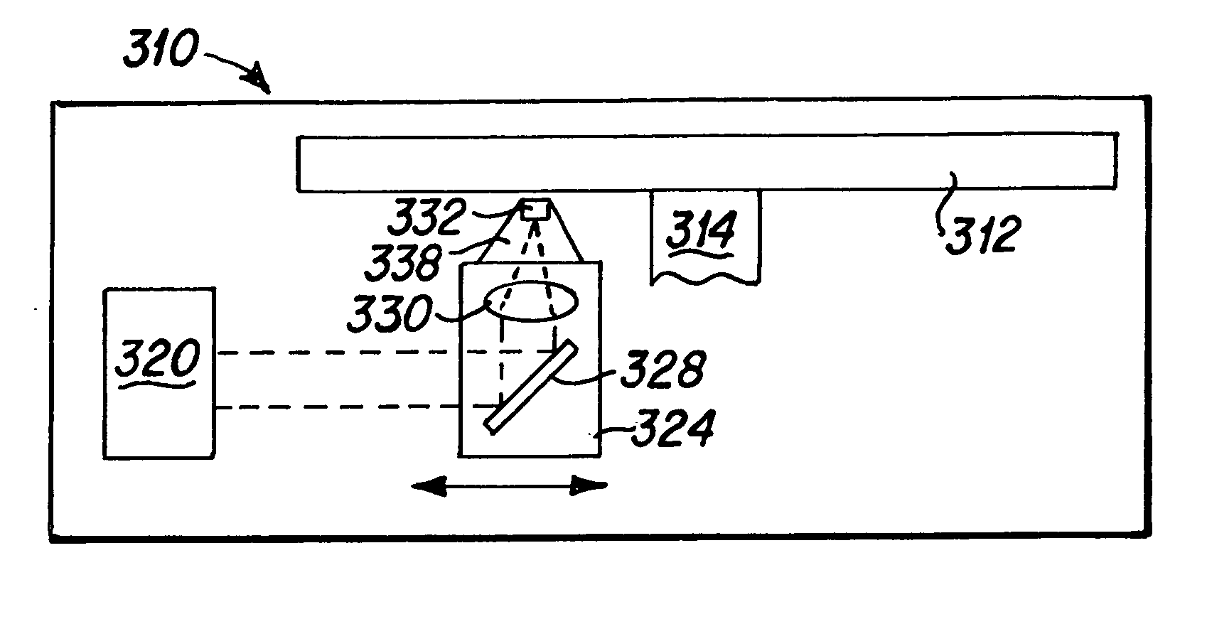
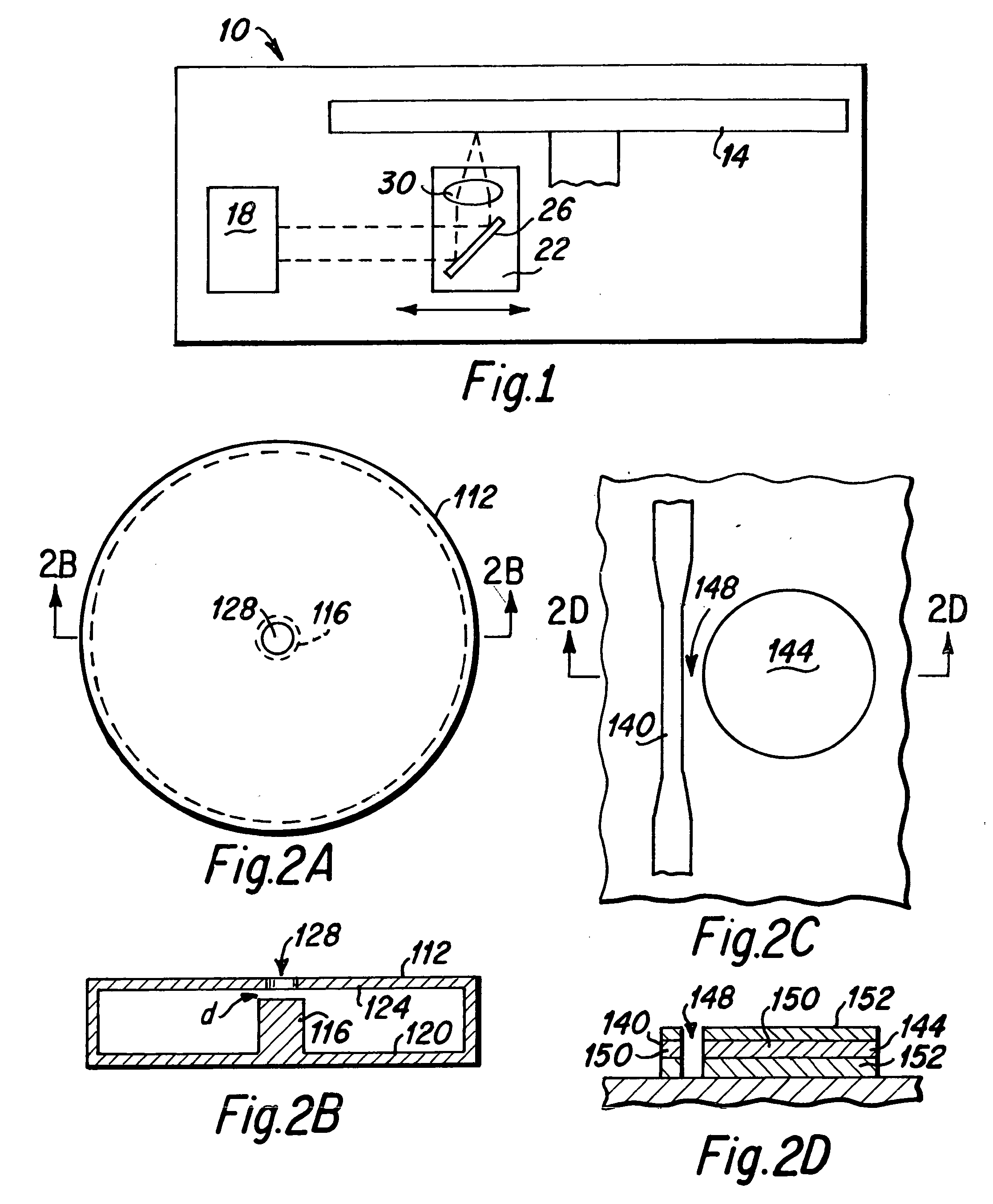
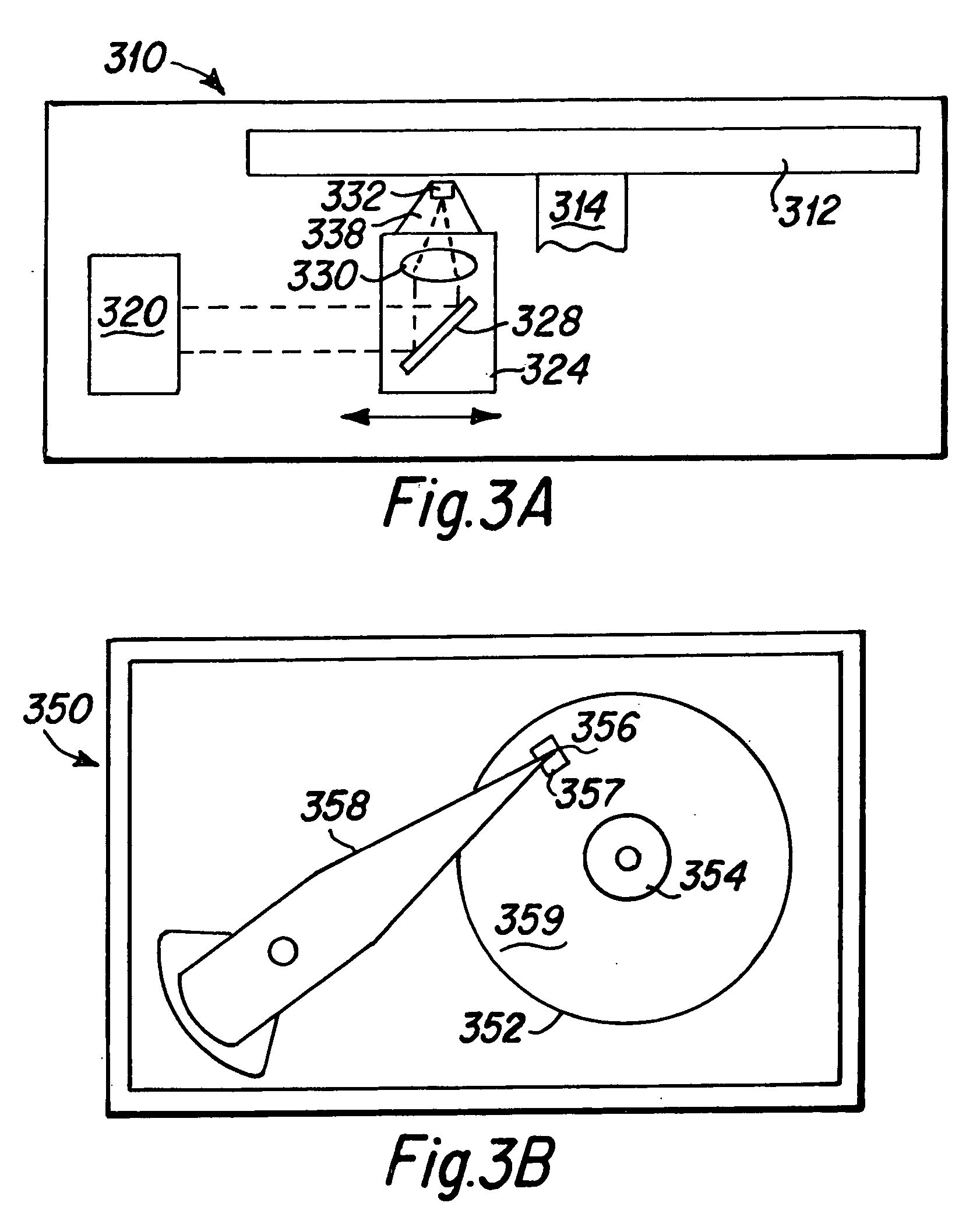
[0046] A simplified diagram of an optical drive 310 of the present invention having a linear actuator for supporting an optical reading head of the present invention is presented in FIG. 3A. This optical drive 310 may include similar components to the prior art linear optical drive 10 depicted in FIG. 1. As depicted in FIG. 3A, the linear optical drive 310 includes at least one optical disk 312 that is rotatably mounted upon a spindle 314. An optical h...


PUM


Abstract

An optical recording head including a media heating device to write and read data to a heat sensitive optical media disk. The media heating device includes an optical energy resonant cavity that produces a high intensity near-field optical spot of subwavelength dimension. Optical energy is coupled into the resonant cavity through a waveguide that is placed proximate the cavity, and optical energy is coupled out of the cavity through an aperture that is placed proximate an antinode or post within the cavity. In reading data from the optical media, a photodetector is placed at the end of the waveguide. Optical energy emitted from the end of the waveguide is influenced by the reflectivity of the media data bit, and is interpreted as the data bit signal.

Description

BACKGROUND OF THE INVENTION [0001] 1. Field of the Invention [0002] The present invention relates generally to optical recording heads that are utilized with optical disk data storage devices, and more particularly to the design and fabrication of a recording head having an optical wavelength resonant cavity media heating device formed therein. [0003] 2. Description of the Prior Art [0004] Optical drives generally include one or more rotatable data storage disks having a data storage media layer formed thereon, and data in the form of small areas, termed data bits are written onto the media layer of the disks by a recording head. Optical recording is essentially a thermal process where the thermal energy is delivered to the media optically by means of a small focused spot of light. The size of the spot generally determines the bit size, and the route to higher data areal recording density is to produce smaller spot sizes. The technology of optical recording is outlined below, and is...

Claims


Application Information

Patent Timeline
IPC IPC(8): G11B5/09G11B7/12G11B7/135
CPCG11B7/00458G11B7/1206G11B7/1387G11B7/124
Inventor POON, CHIE CHINGSTRAND, TIMOTHY CARL
Owner HITACHI GLOBAL STORAGE TECH NETHERLANDS BV
Why Eureka
Try Eureka