Buried channel type transistor having a trench gate and method of manufacturing the same

a technology of buried channel type transistor and trench gate, which is applied in the direction of transistors, electrical devices, semiconductor devices, etc., can solve the problems of affecting the channel region of drain voltage, reducing the gate voltage of the buried channel type p-mos transistor, so as to prevent the diffusion of impurities and facilitate manufacturing.

Active Publication Date: 2006-08-03
SAMSUNG ELECTRONICS CO LTD
View PDF7 Cites 5 Cited by
  • Summary
  • Abstract
  • Description
  • Claims
  • Application Information

AI Technical Summary

Benefits of technology

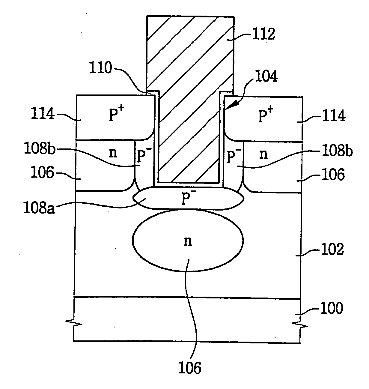
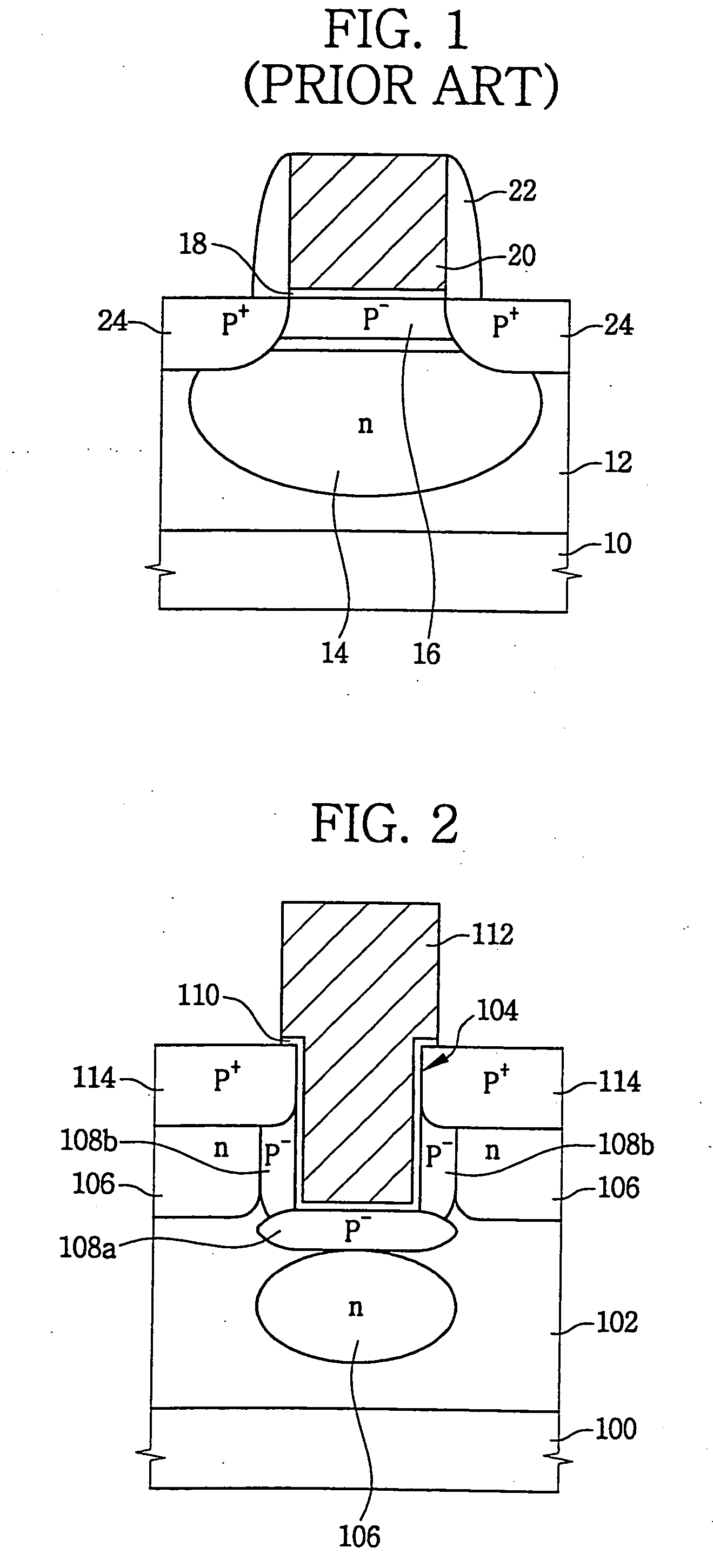
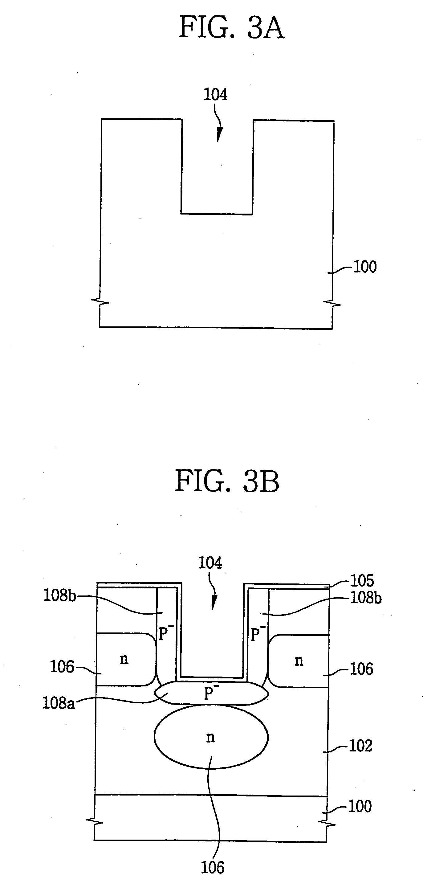
[0024] According to the present invention, the stopper regions prevent surface depletions of the threshold voltage control regions adjacent to the sidewall and bottom face of the trench. The stopper regions also prevent diffusion of impurities included in the source / drain regions. In addition, the threshold voltage control regions prevent the increase of a threshold voltage of the channel region formed adjacent to the sidewall of the trench due to the formation of the stopper regions. Furthermore, a buried channel type transistor having the recess type channel regions may be easily manufactured because several ion implantation processes for the formations of a well, the stopper regions, source / drain regions may be performed in one chamber.

Problems solved by technology

It, however, has disadvantages in that a gate voltage of the buried channel type P-MOS transistor may be decreased and a short channel effect may easily occur in the buried channel type P-MOS transistor because a p-n junction is not formed near a boundary between a silicon substrate.
Furthermore, a gate oxide layer and a drain voltage may strongly affect the channel region.
However, manufacturing processes for the dual gate structure may be complicated and manufacturing cost for forming the dual gate structure may be greatly increased because the N-MOS transistor and the P-MOS transistor are separately formed using additional photo masks and additional photolithography processes.

Method used


Image

  • Buried channel type transistor having a trench gate and method of manufacturing the same
  • Buried channel type transistor having a trench gate and method of manufacturing the same
  • Buried channel type transistor having a trench gate and method of manufacturing the same

Examples


Embodiment Construction

[0032] The present invention now will be described more fully hereinafter with reference to the accompanying drawings, in which embodiments of the invention are shown. This invention may, however, be embodied in many different forms and should not be construed as limited to the embodiments set forth herein; rather, these embodiments are provided so that this disclosure will be thorough and complete, and will fully convey the scope of the invention to those skilled in the art. In the drawings, the thickness of layers and regions are exaggerated for clarity. Like reference numerals refer to similar or identical elements throughout. It will be understood that when an element such as a layer, region or substrate is referred to as being “on” or “onto” another element, it can be directly on the other element or intervening elements may also be present.

[0033]FIG. 2 is a cross-sectional view illustrating a buried channel type P-MOS transistor in accordance with some embodiments of the pres...


PUM


Abstract

In a method of manufacturing a buried channel type transistor, a trench is formed at a surface portion of a substrate. A first and a second threshold voltage control regions are formed at portions of the substrate beneath a bottom face of the trench and adjacent to a sidewall of the trench, respectively. A gate electrode filling the trench is formed. Source / drain regions are formed at portions of the substrate adjacent to the sidewall of the gate electrode. Stopper regions are formed at portions of the substrate beneath the source / drain regions and beneath the first and second threshold voltage control regions, respectively. The buried channel type transistor has a high breakdown voltage between the source / drain regions although a threshold voltage thereof is low.

Description

CROSS REFERENCE TO RELATED APPLICATION [0001] This is a Divisional of U.S. patent application Ser. No. 10 / 839,951, filed on May 5, 2004, now pending, which claims priority from Korean Patent Application No. 2003-29156, filed on May 7, 2003, the contents of which are incorporated by reference.BACKGROUND OF THE INVENTION [0002] 1. Field of the Invention [0003] The present invention relates to a buried channel type transistor having a trench gate and a method of manufacturing the buried channel type transistor. More particularly, the present invention relates to a buried channel type transistor having a trench gate, and a method of manufacturing the buried channel type transistor. [0004] 2. Description of the Related Art [0005] As semiconductor devices are highly integrated, sizes of active regions on which MOS transistor are formed may be greatly reduced. Thus, the MOS transistor formed in the active region has a channel length well below a micrometer (μm). When the MOS transistor has...

Claims


Application Information

Patent Timeline
Patent Type & Authority Applications(United States)
IPC IPC(8): H01L29/94H01L21/336H01L21/8242H01L29/10H01L29/78
CPCH01L29/105H01L29/1083H01L29/6659H01L29/66621H01L29/7834H01L21/18
Inventor KIM, JI-YOUNGLEE, CHANG-SUB
Owner SAMSUNG ELECTRONICS CO LTD
Why Eureka
Try Eureka