Control of a multi-sectored antenna system to improve channel efficiency

a multi-sectored antenna and control technology, applied in the field of control of antennas, can solve problems such as problems such as the inability to achieve adequate rf coverage at a desired data throughput, the inability to control the range and data rate of such systems, and the inability to control the reception of client devices, so as to achieve a higher data rate and data rate

Inactive Publication Date: 2006-08-03
MICROSOFT TECH LICENSING LLC
View PDF23 Cites 70 Cited by
  • Summary
  • Abstract
  • Description
  • Claims
  • Application Information

AI Technical Summary

Benefits of technology

[0008] Thus, the present invention was developed to achieve the benefits of a directional antenna, without the problems noted above. Instead of using a plurality of different directional antennas and a different transceiver for each directional antenna, the present invention selectively controls the direction used for communication by employing a multi-sector antenna that is steerable in regard to the direction in which it transmits and receives RF wireless signals. This antenna is electronically steered so that a selected sector is activated (or so that the beam of the antenna is steered in a selected direction). The selected sector then transmits and receives in this direction, which is defined by a phased array antenna disposed on the sector. By selecting the sector associated with a direction that provides the optimal signal strength or some other criterion that is indicative of signal quality, it is possible to achieve a much higher data rate than is possible when transmitting or receiving in all directions at the same time (for a given transmit power). The direction in which communications occur can thereby be dynamically controlled to enable streaming video or other data that requires a higher data rate to be effectively communicated to or from the wireless device.

Problems solved by technology

As an increasing number of computer users install wireless networks that meet the Institute of Electrical and Electronics Engineers (IEEE) 802.11 specifications in their homes and workplaces, it has become apparent that the performance (i.e., range and data rate) of such systems often fails to meet their expectations.
Structures built of stone or brick, or which contain blocking interior elements, such as a fireplace, mirror, refrigerator, or other large metal or masonry furnishings, often cause problems in achieving adequate RF coverage at a desired data throughput.
Also, the reception at a client device can be disrupted as a person or other object moves through the signal path to the access point, or if the client device, which is often a laptop or other portable computing device, moves even a few centimeters.
However, these buffers cause a lag in the media data feed (latency), increase memory requirements, and generally make a wireless system more complex than is necessary.
Frequently, the only way to achieve a desired coverage and throughput in an office or home is to add more access points so that the distance and / or intervening structural elements between the access points and the clients devices are reduced, which means higher wiring costs to run Ethernet cabling to the additional access points and greater equipment costs for each added access point.
Increasing transmitter power is typically not an option due to regulatory limitations and / or because significantly increased power consumption is not acceptable for a battery powered side of a link.
However, the direction in which the RF energy needs to be transmitted or received is not fixed in most wireless systems, because a fixed access point must be able to maintain communications with moving client devices, or communicate with client devices that are located at different positions scattered around the access point.
Such systems are generally too costly for home or small business use, however.
Unfortunately, these systems are typically large and very expensive, and consequently, have generally not appeared in consumer products.
This technology is also beginning to appear in commercial access points intended for installation in large scale commercial applications, such as at airports or in universities, but suitable systems still cost thousands of dollars.

Method used


Image

  • Control of a multi-sectored antenna system to improve channel efficiency
  • Control of a multi-sectored antenna system to improve channel efficiency
  • Control of a multi-sectored antenna system to improve channel efficiency

Examples


Embodiment Construction

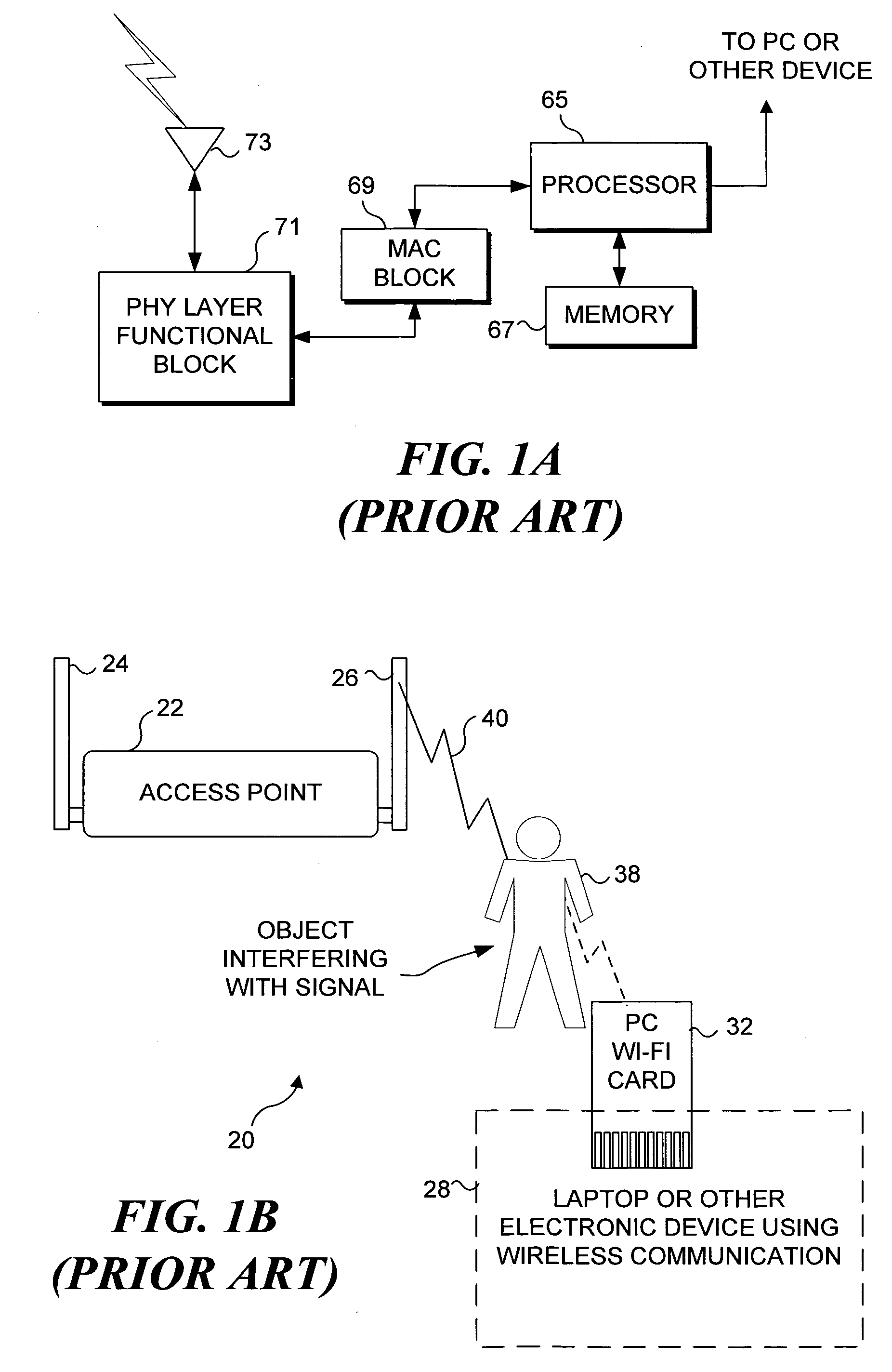
[0032]FIG. 1A (Prior Art) is a simplified functional block diagram of a typical wireless device like that usable with the present invention. This wireless device includes a processor 65 that is coupled to a PC or other computing device (not shown) so that data that has either been received or that is being provided for transmission to another wireless device can be communicated to the processor. Processor 65 is coupled to a memory 67, which stores machine instructions for processing the data and for carrying out other functions. A media access control (MAC) block 69 and physical (PHY) layer functional block 71 are disposed between processor 65 and an RF omnidirectional antenna 73. Although a second omnidirectional antenna is typically provided, only one is used at a time. This conventional wireless device does not include a directional antenna, and it is subject the problems noted above communicating over a wireless network. An example of one of these problems is illustrated in FIG....


PUM


Abstract

A wireless device is coupled to a multi-sector antenna that includes a plurality of different sectors, any of which can be activated to transmit and receive in a desired direction specific to that sector. Optionally, an omnidirectional antenna is included for initially establishing a wireless connection with another wireless device, such as an access point. A parameter indicative of signal quality, such as throughput or received signal strength indication (RSSI) is determined by polling with each antenna sector to establish a prioritized candidate list. If a receive Trigger becomes active in response to a parameter falling below a threshold level, a new candidate sector is selected from the current list based upon a next-best signal quality. The directionality of the multi-sector antenna provides a substantially higher data rate compared to that of the conventional omnidirectional antenna.

Description

FIELD OF THE INVENTION [0001] The present invention generally pertains to control of an antenna used on a wireless network, and more specifically, to control of a multi-sector antenna that is coupled to a wireless device and can be controlled to communicate with another wireless device in a direction selected from a plurality of different directions. BACKGROUND OF THE INVENTION [0002] As an increasing number of computer users install wireless networks that meet the Institute of Electrical and Electronics Engineers (IEEE) 802.11 specifications in their homes and workplaces, it has become apparent that the performance (i.e., range and data rate) of such systems often fails to meet their expectations. Structures built of stone or brick, or which contain blocking interior elements, such as a fireplace, mirror, refrigerator, or other large metal or masonry furnishings, often cause problems in achieving adequate RF coverage at a desired data throughput. Throughput can be very important wh...

Claims


Application Information

Patent Timeline
Patent Type & Authority Applications(United States)
IPC IPC(8): H04Q7/00H04W16/24
CPCH04W16/24H04W72/046
Inventor KING, WAYNE G.RANTA, CRAIG STEVENGIAIMO, EDWARD C. IIIBRENNAN, JAMESSTEGNER, STEPHEN M.RUSSO, DAVID WILLIAMMURZANSKI, CHRIS A.
Owner MICROSOFT TECH LICENSING LLC
Why Eureka
Try Eureka