Video surveillance system

Inactive Publication Date: 2006-08-03
WILIFE
View PDF37 Cites 245 Cited by
  • Summary
  • Abstract
  • Description
  • Claims
  • Application Information

AI Technical Summary

Benefits of technology

[0012] An exemplary embodiment of the first camera includes a housing and an image capture system, which is supported by the housing and generates an analog video signal. The first camera also includes a processor enclosed in the housing and coupled to the image capture system. The processor transforms the analog video signal into a video data stream, and the processor includes a motion detection module for indicating a segment of the video data stream during which a motion-based event occurred. The first camera includes a transceiver coupled to the processor for sending the video data stream over a dual use medium. In particular, in exemplary embodiments of the first camera, some of the video processing tasks are performed by the camera to reduce use of the processing resources on the computing device, allowing other applications to operate normally and seamlessly.

Problems solved by technology

Many of these systems, however, can be difficult and costly to install, reducing their practicality in many markets.
In addition to the difficulty and cost of setting up a traditional video surveillance system, transmission of streaming video over a conventional network generally exhibits some undesirable properties resulting from the unpredictability of the transport delay through the transport medium.
Even when the advanced user reduces the buffering delay to the shortest possible value, transport delays and connection times are quite high.
For viewing pre-recorded video, the delay means that a user must wait for several seconds before the video begins.
For a system intended for viewing live-camera images, there are two significant drawbacks to this delayed approach.
This can be confusing to a user, and the penalty for network errors is many seconds of lost video.
Secondly, even after video is finally visible, the temporal lag between the live camera scene and the viewed scene is very disconcerting to a viewer who sees both the live scene and the video image, as is common with a video surveillance system.
Furthermore, most traditional video surveillance systems require a dedicated computer system to handle all of the compute-intensive tasks associated with handling multiple simultaneous video streams.
These tasks can consume the available central processing unit (CPU) processing power on most modern computing devices (PC), reducing the resources available for other normal computing tasks such as word processing, spread sheet, budgeting, and other common applications.

Method used


Image

  • Video surveillance system
  • Video surveillance system
  • Video surveillance system

Examples


Embodiment Construction

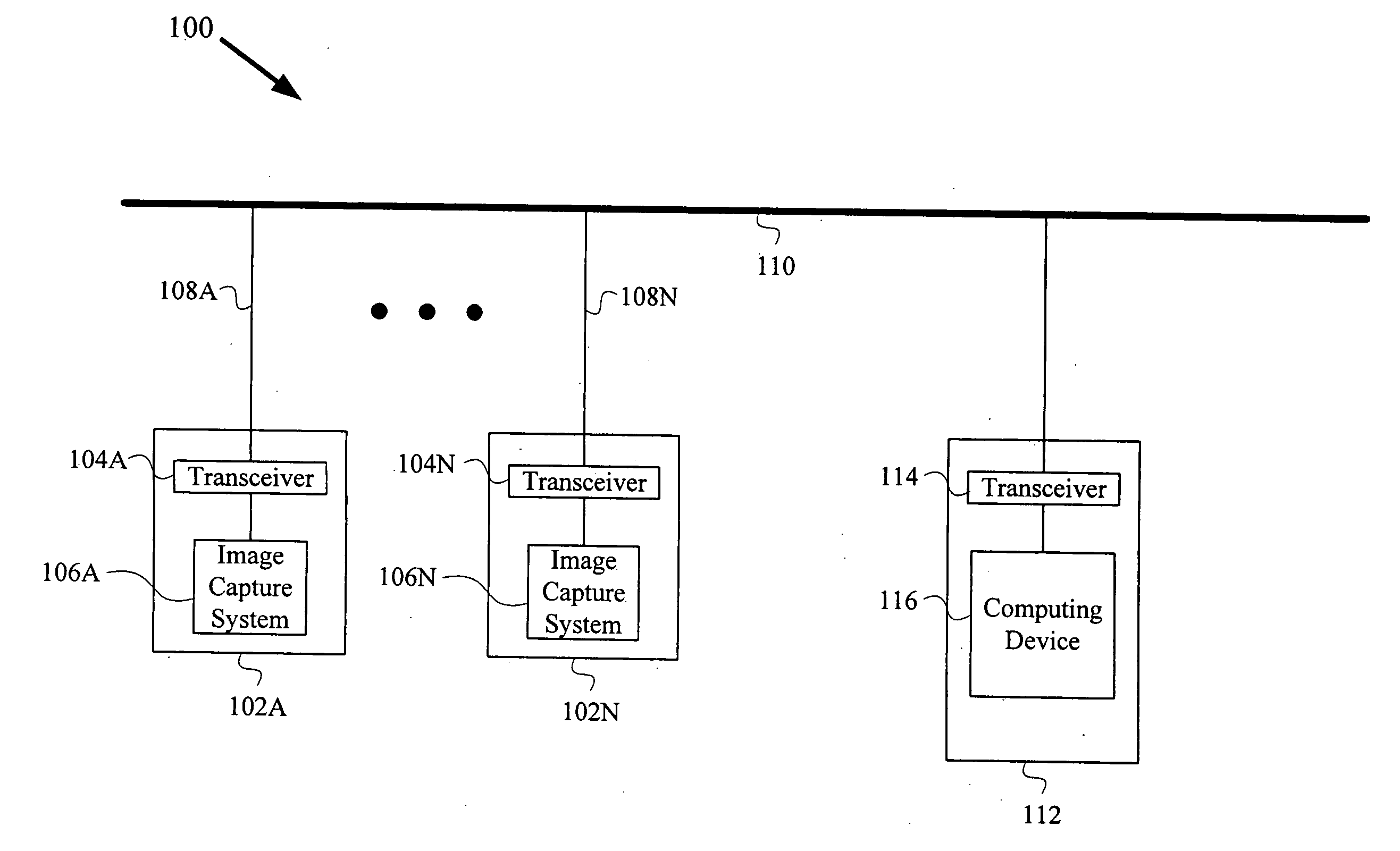
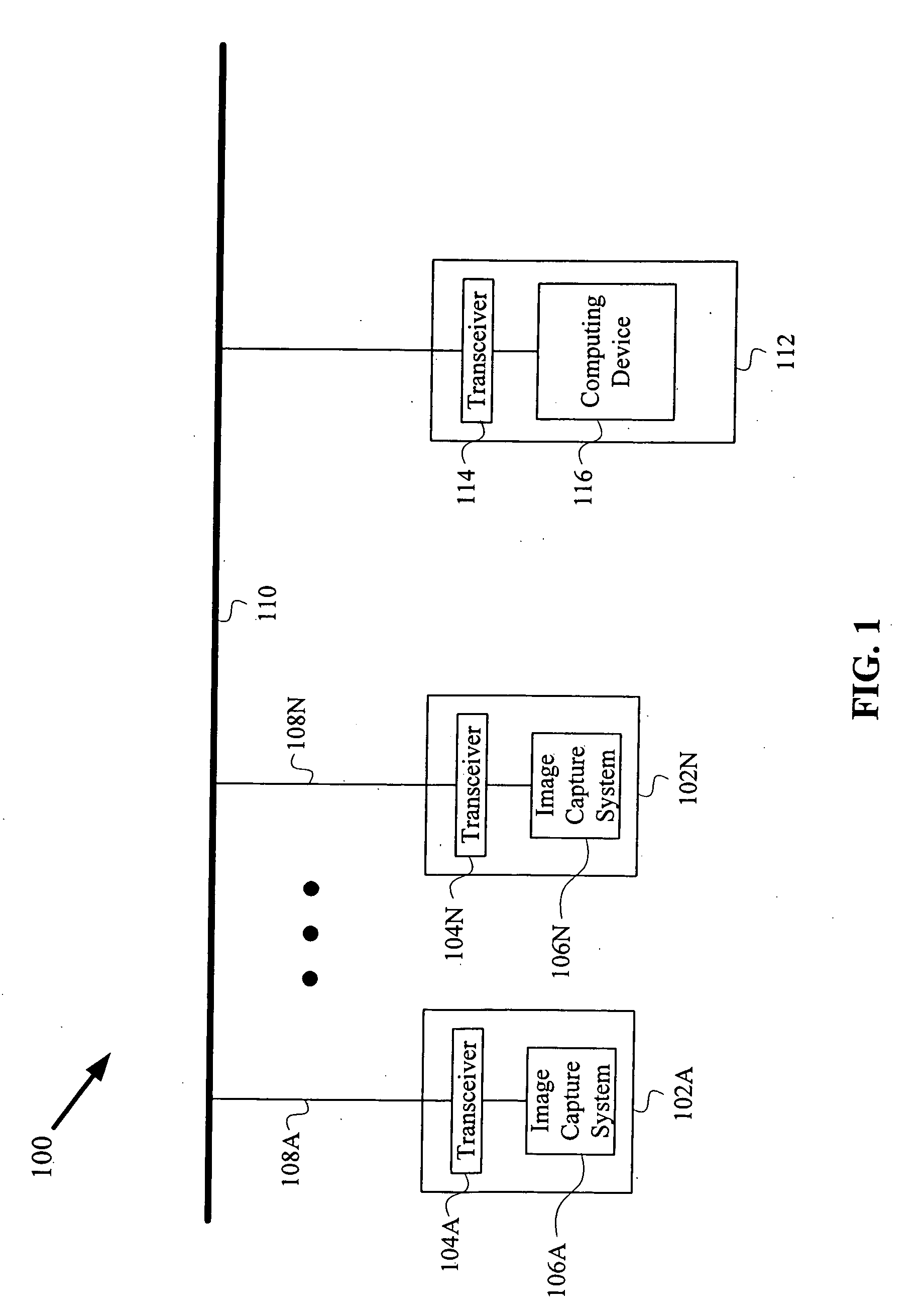
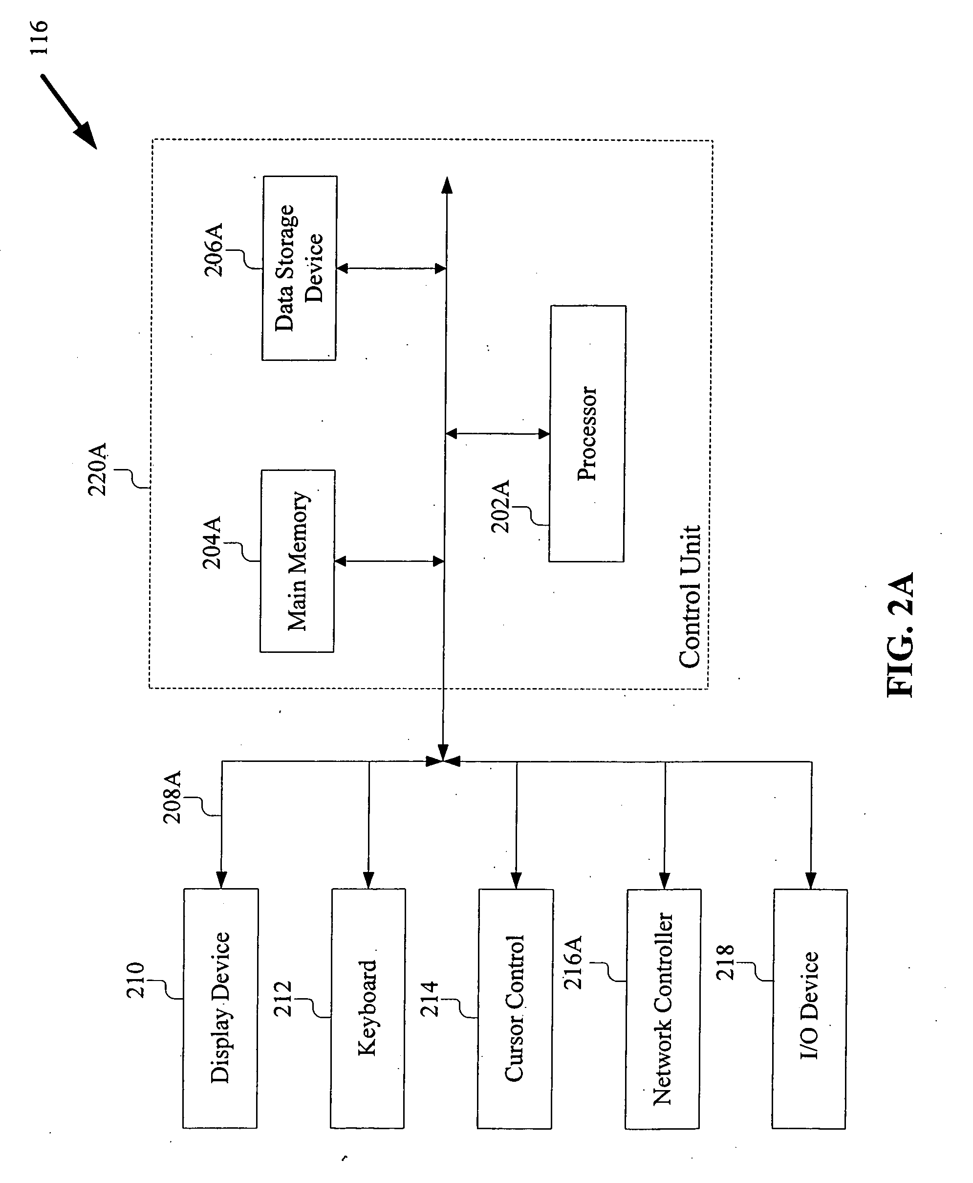
[0035] Reference will now be made in detail to several embodiments of the present invention, examples of which are illustrated in the accompanying figures. Reference in the specification to “one embodiment” or “an embodiment” means that a particular feature, structure, or characteristic described in connection with the embodiment is included in at least one embodiment of the invention. The appearances of the phrase “in one embodiment” in various places in the specification are not necessarily all referring to the same embodiment. Wherever practicable, similar or like reference numbers may be used in the figures and may indicate similar or like functionality. The figures depict embodiments of the present invention for purposes of illustration only. One skilled in the art will readily recognize from the following description that alternative embodiments of the structures and methods illustrated herein may be employed without departing from the principles of the invention described her...


PUM


Abstract

A video surveillance system includes one or more cameras communicatively coupled to a control system via a dual use medium. The video surveillance system includes a setup mode, a live viewing mode, a record mode, and a search / playback mode, some of which may operate simultaneously. In a live viewing mode, a user can view video data from one or more cameras using a graphical user interface. In the record mode, a user can independently set the record modes and schedules of the cameras, specify multiple motion detection zones per camera, and record in panic mode. In the search / playback mode, a user can search for and view, previously recorded video segments and perform file operations on the recorded video segments.

Description

CROSS REFERENCE TO RELATED APPLICATIONS [0001] This application claims priority under 35 U.S.C. § 119(e) to U.S. Provisional Patent Application No. 60 / 641,392, titled “Video Surveillance System” to Thomas R. Rohlfing, et al., and filed Jan. 4, 2005; and to U.S. Provisional Patent Application No. 60 / 661,305, titled “Security Camera With Adaptable Connector For Coupling To Track Lighting And Back-Up System For Fault Tolerance” to Andrew Hartsfield, et al., filed Mar. 10, 2005; and to U.S. Provisional Patent Application No. 60 / 681,003, titled “Modular Design For A Security System” to Andrew Hartsfield, et al., filed May 12, 2005, the contents of each are herein incorporated by reference.BACKGROUND OF THE INVENTION [0002] 1. Field of the Invention [0003] The present invention generally relates to the field of video surveillance systems, and more specifically, to software-controlled video surveillance systems. [0004] 2. Description of the Related Arts [0005] Traditional video surveillanc...

Claims


Application Information

Patent Timeline
IPC IPC(8): H04N11/04H04N7/18H04N9/47H04N11/02H04N7/12H04B1/66
CPCG08B13/19632G08B13/19656G08B13/19673G08B13/1968G08B13/19682G08B13/19691H04N7/181H04N21/485
Inventor ROHLFING, THOMAS R.NORING, JEREMY A.LANCASTER, JEFFREY B.TREE, EVAN I. F.HARTSFIELD, ANDREW J.
Owner WILIFE
Why Eureka
Try Eureka