
Valve and auxiliary exhaust system for high efficiency steam engines and compressed gas motors
a steam engine and compressed gas technology, applied in the field of steam engines, can solve the problem of more steam passing through the engine, and achieve the effect of improving the operation control
- Summary
- Abstract
- Description
- Claims
- Application Information
AI Technical Summary
Benefits of technology
Problems solved by technology
Method used
Image

Examples
Embodiment Construction
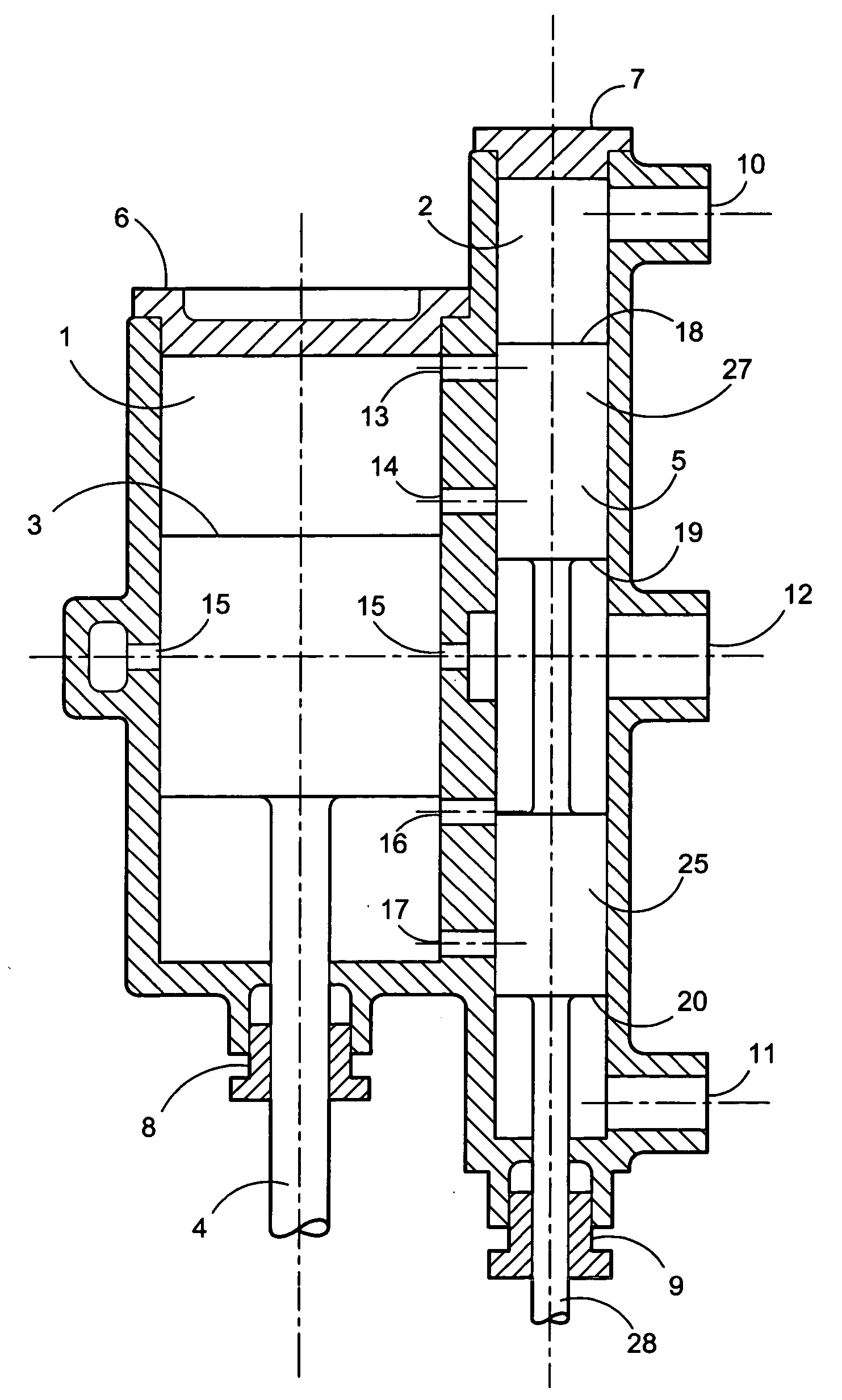
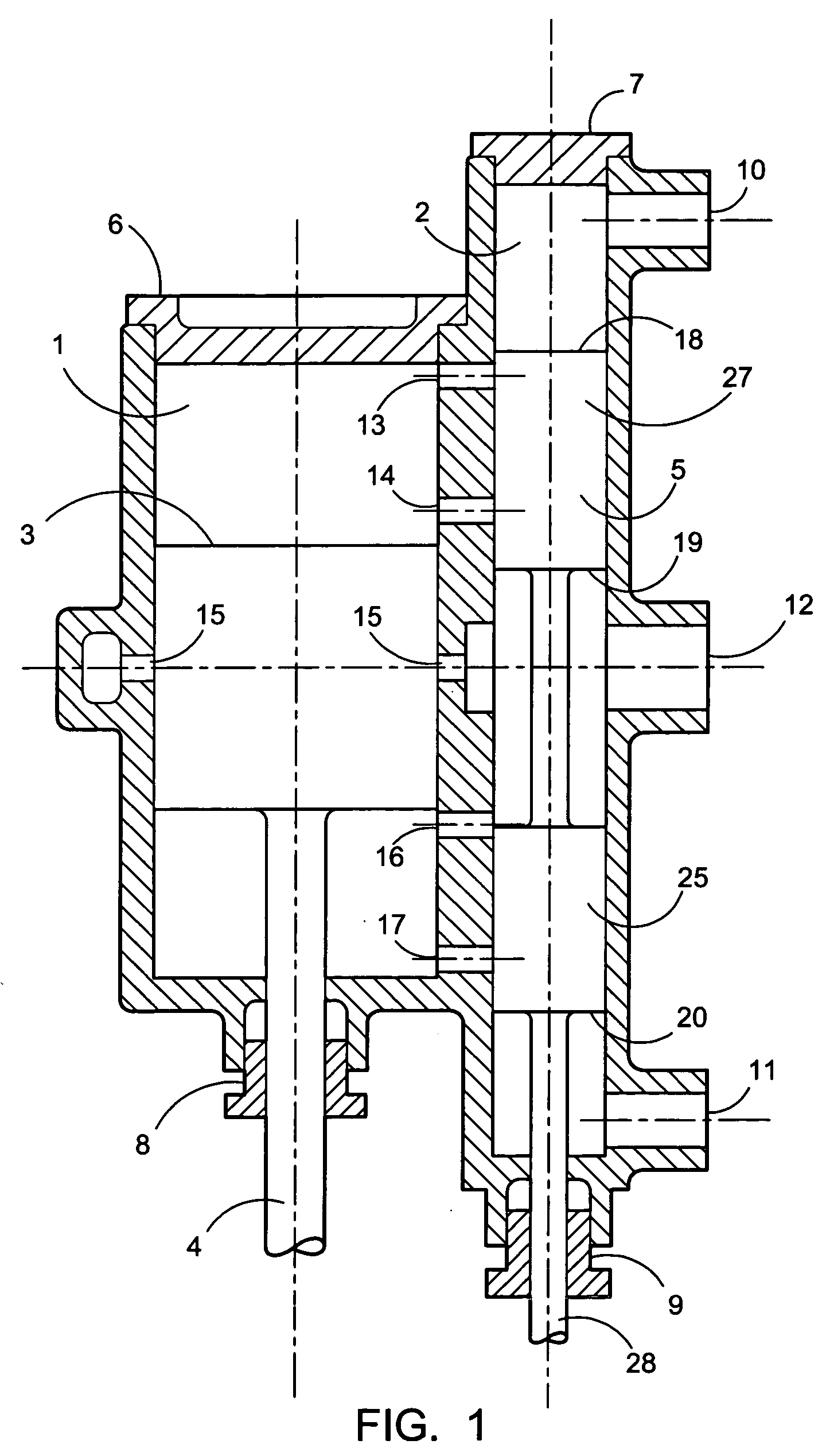
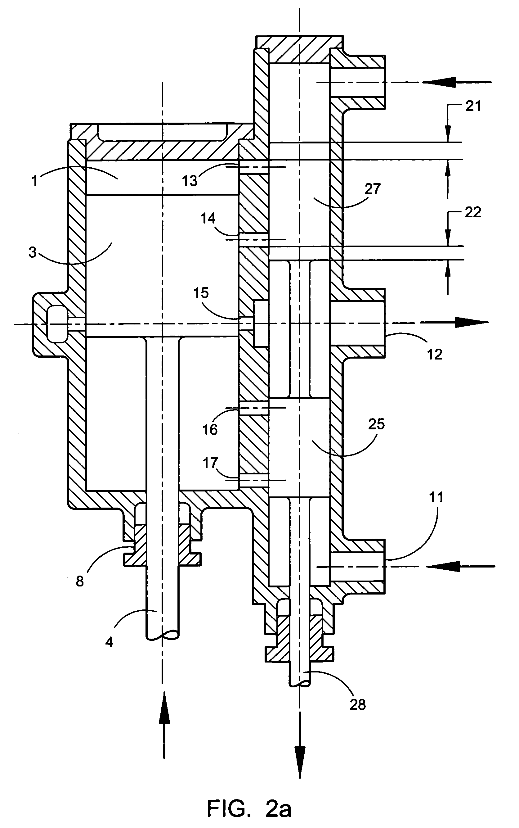
[0031]FIG. 1, shows the cylinder arrangement for an embodiment of the device for employment with a uniflow double-acting steam engine including the herein disclosed and described novel valve design, which used in conjunction with a conventional harmonic valve drive mechanism, forms the main part of this invention. Not shown is the crankcase containing the connecting rod, crosshead, valve motion and other attendant parts of the engine for which the disclosed device is adapted for engagement. These latter parts may be conventional in design.
[0032] The main parts shown are the cylinder 1, the valve chest 2, and the piston, 3, which would best be fitted with piston rings (not shown). Also shown in FIG. 1 is the piston rod 4, and the slide valve 5, showing the continuous exterior surface to contact the valve chest and which also would be fitted with sealing rings but which are not shown. Number 6 depicts the cylinder head and the valve chest cap is shown as number 7. The piston rod seal...
PUM
 Abstract
Description
Claims
Application Information