
Porous membranes for medical implants and methods of manufacture

a technology of porous membranes and implants, applied in the field of porous membranes, can solve the problems of unsteady collocation of fibers, inability to tightly control the pore size and pore pattern of the resulting membrane, and foregoing spinning processes

Inactive Publication Date: 2006-08-10
ABBOTT LAB VASCULAR ENTERPRISE
View PDF93 Cites 43 Cited by
  • Summary
  • Abstract
  • Description
  • Claims
  • Application Information

AI Technical Summary

Benefits of technology

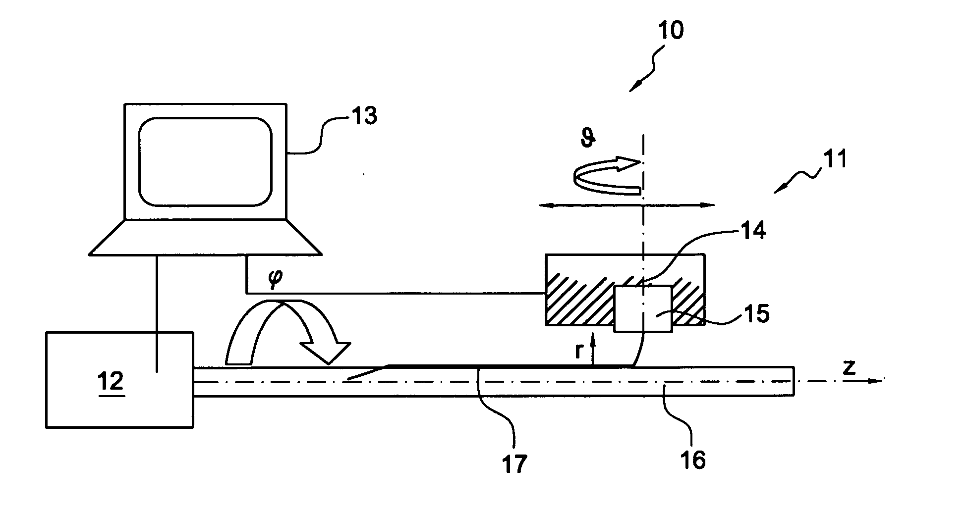
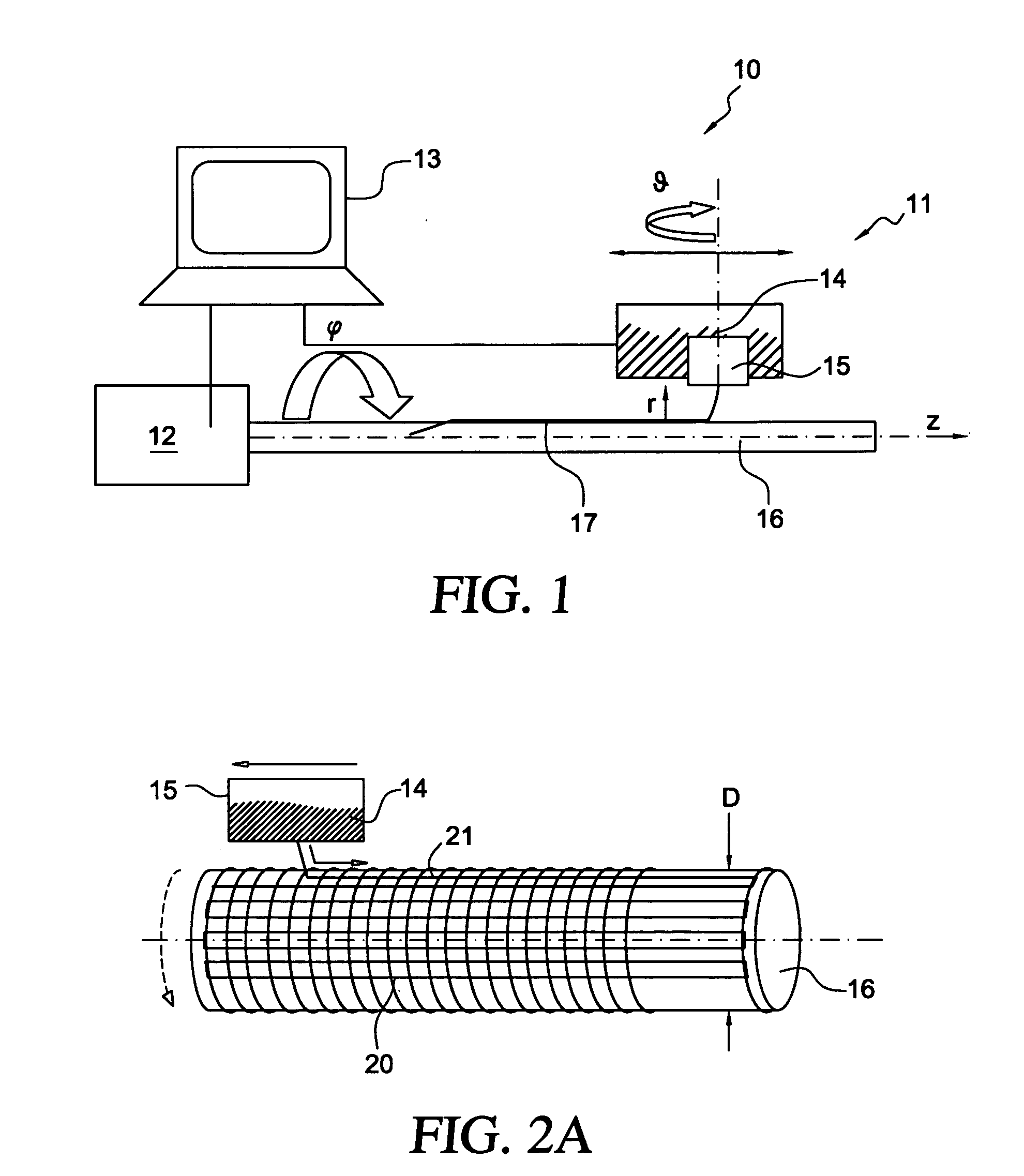
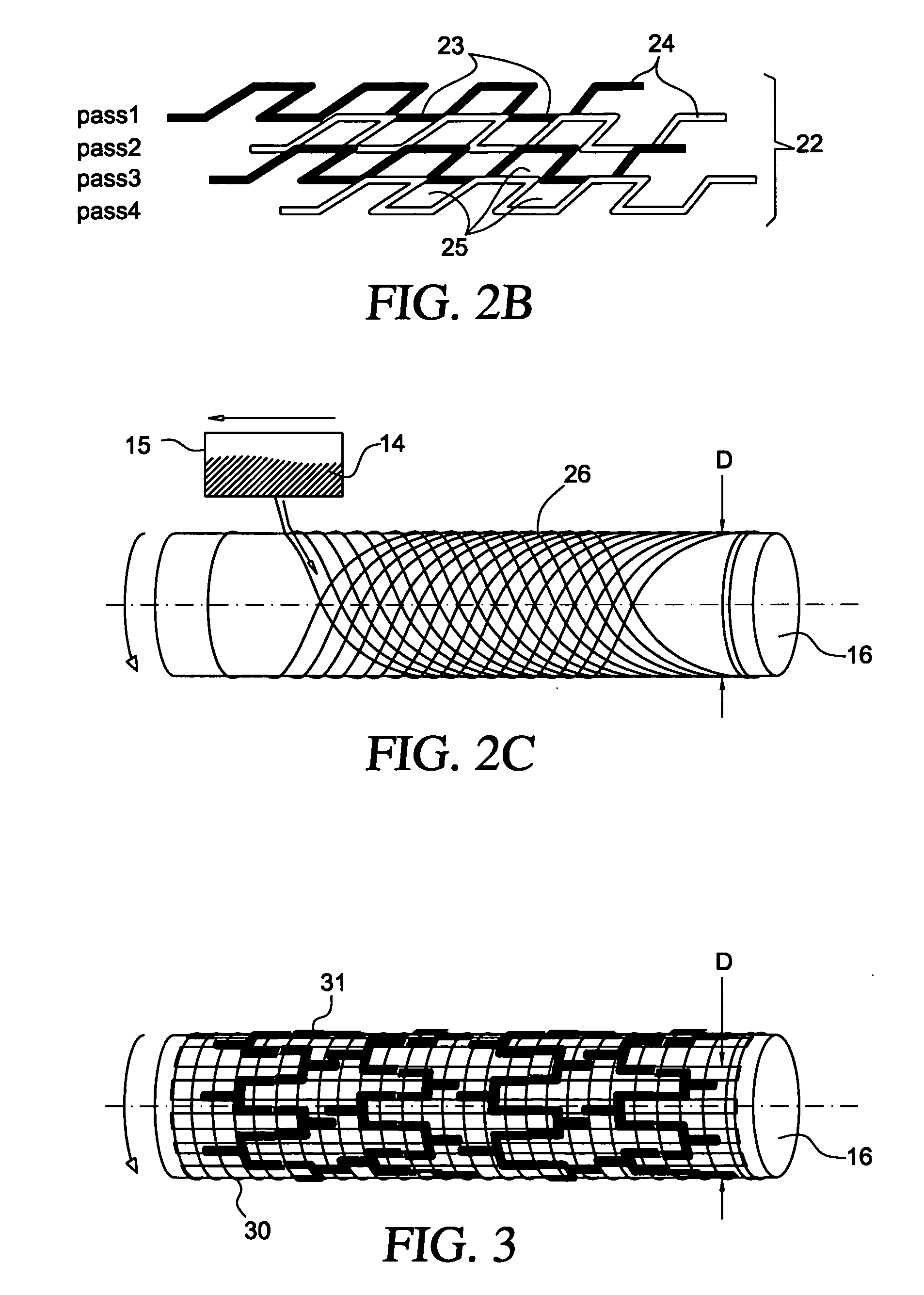
[0017] These and other objects of the present invention are accomplished by providing a membrane comprising a plurality of fibers that are deposited onto a substrate with a predetermined and reproducible pattern. The substrate may be either a mandrel or a surface of an implantable device, such as a stent. In a preferred embodiment, the fibers comprise a polymer that is sufficiently elastic and robust that the membrane follows the movements of the stent from loading onto a stent delivery system to deployment and implantation, without adversely affecting the performance of the membrane of the stent.
[0020] In accordance with another aspect of the present invention, the membrane may comprise composite fibers having a viscous sheath co-extruded around a solid core component, or alternatively may comprise co-extruded viscous components. In this manner, a membrane may be created wherein the individual fibers are loaded with a desired bioactive agent, such as a drug, that elutes from the matrix of the membrane without resulting in substantial degradation of the mechanical properties of the membrane.

Problems solved by technology

All of the foregoing spinning processes suffer from an inability to tightly control the pore size and pore pattern of the resulting membranes.
More specifically, lateral deviation of the fibers using previously known spinning techniques has resulted in unsteady collocation of the fibers and the need to deposit multiple layers to ensure adequate coverage.
Consequently, previously-known techniques produce either stiff membranes formed of multiple layers and unsatisfactory porosity, or porous, elastic membranes with insufficient strength.

Method used


Image

  • Porous membranes for medical implants and methods of manufacture
  • Porous membranes for medical implants and methods of manufacture
  • Porous membranes for medical implants and methods of manufacture

Examples


Embodiment Construction

[0028] The present invention generally relates to medical implants, such as stents, having a porous membrane and the methods of making such membranes and medical implants. In accordance with the present invention, polymer membranes are provided that have well-defined pores based on a controlled deposition of fibers onto a substrate. In this manner a permeable membrane having a predetermined pore size and distribution may be obtained.

[0029] Acute as well as late embolization are a significant threat during and after intravascular interventions such as stenting in saphenous vein grafts (SVG) and carotid arteries, where released particles can lead to major cardiac attacks or strokes, respectively. Covered stents for treatment of atherosclerotic lesions constructed according to the present invention comprise a porous membrane bonded to an exterior surface, and interior surface, or both, of a stent. Advantageously, the covered stent of the present invention may serve both to reduce embo...


PUM

PropertyMeasurementUnit
Angleaaaaaaaaaa
Lengthaaaaaaaaaa
Lengthaaaaaaaaaa

Abstract

The present invention involves porous polymer membranes, suitable for use in medical implants, having controlled pore sizes, pore densities and mechanical properties. Methods of manufacturing such porous membranes are described in which a continuous fiber of polymer is extruded through a reciprocating extrusion head and deposited onto a substrate in a predetermined pattern. When cured, the polymeric material forms a stable, porous membrane suitable for a variety of applications, including reducing emboli release during and after stent delivery, and providing a source for release of bioactive substances to a vessel or organ and surrounding tissue.

Description

REFERENCE TO RELATED APPLICATIONS [0001] The present application is a continuation-in-part of U.S. patent application Ser. No. 10 / 859,636, filed Jun. 3, 2004, which is a continuation of U.S. patent application Ser. No. 09 / 967,789, filed Sep. 28, 2001. This application also claims the benefit of priority from U.S. provisional patent application Ser. No. 60 / 637,495, filed Dec. 20, 2004.FIELD OF THE INVENTION [0002] The present invention relates to porous membranes suitable for covering medical implants such as stents for intravascular delivery, implants covered with such membranes and methods for making the porous membranes. BACKGROUND OF THE INVENTION [0003] Covered stents for implantation into a body vessel, duct or lumen generally include a stent and a cover attached to the stent. A porous structure of the cover, depending on the porosity, may enhance tissue ingrowth after the covered stent has been implanted. A porous structure affixed to an implantable device also may serve as a ...

Claims


Application Information

Patent Timeline
IPC IPC(8): B32B37/00A61F2/90B29C48/08B29C48/151B29C48/92
CPCA61F2/01Y10T428/24298A61F2/91A61F2/915A61F2002/91508A61F2002/91533A61F2002/91558B29C47/0021B29C47/0042B29C47/021B29C47/92B29C2947/92571B29C2947/9258B29C2947/9259B29C2947/926B29C2947/92609B29C2947/92628B29C2947/92695B29C2947/92904B29K2023/06B29K2023/12B29K2027/18B29K2067/00B29K2071/00B29K2075/00B29K2077/00B29K2105/04B29K2105/108B29L2031/7532B29L2031/755D04H3/07Y10T428/24273Y10T428/24306A61F2/90B29C48/92B29C48/08B29C48/0012B29C48/151B29C2948/92571B29C2948/9258B29C2948/9259B29C2948/926B29C2948/92609B29C2948/92628B29C2948/92695B29C2948/92904
Inventor FIERENS, JOOST J.HUESLER, ERHARD J.ZUCKER, ARIKMARCOUX, ERICNICAISE, PHILIPPE
Owner ABBOTT LAB VASCULAR ENTERPRISE
Learn More