Light-emitting discharge tube, method of fabricating the same, and protective film forming apparatus

a technology of light-emitting discharge tube and manufacturing method, which is applied in the direction of discharge tube general techniques, discharge tube coating, gas-filled discharge tube, etc., can solve the problems of easy damage to the surface of glass tube, easy breakage of glass tube, and easy deterioration of glass tube, etc., to achieve excellent discharge characteristics, high fabrication yield, and high reliability

Inactive Publication Date: 2006-08-10
SHINODA PLASMA
View PDF4 Cites 2 Cited by
  • Summary
  • Abstract
  • Description
  • Claims
  • Application Information

AI Technical Summary

Benefits of technology

[0018] In the present invention, by passing the tube body for a light-emitting discharge tube through the through portion that can hold a liquid that is a material of the protective film, a protective film is coated and formed; accordingly, a protective film forming apparatus with a simple structure that is capable of precisely controlling the formation of a protective film is provided.
[0019] According to the present invention, since a protective film is formed on an outer wall surface of a glass tube, the outer wall surface of the glass tube can be prevented

Problems solved by technology

Since the length of the light-emitting discharge tube is extremely long relative to the outside diameter and the wall thickness is also thin, there are problems that the glass tube is susceptible to breakage during the fabrication process and a fabricated light-emitting discharge tube is also susceptible to breakage.
It is found that a surface of a glass tube is flawed during the fabrication process and

Method used


Image

  • Light-emitting discharge tube, method of fabricating the same, and protective film forming apparatus
  • Light-emitting discharge tube, method of fabricating the same, and protective film forming apparatus
  • Light-emitting discharge tube, method of fabricating the same, and protective film forming apparatus

Examples


first embodiment

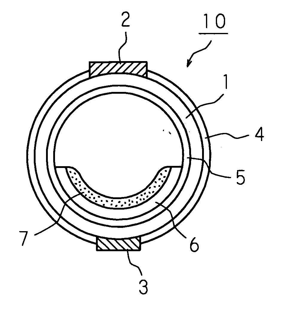
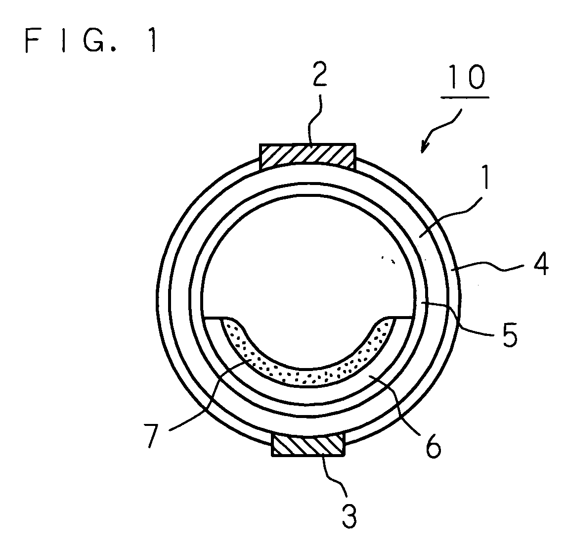
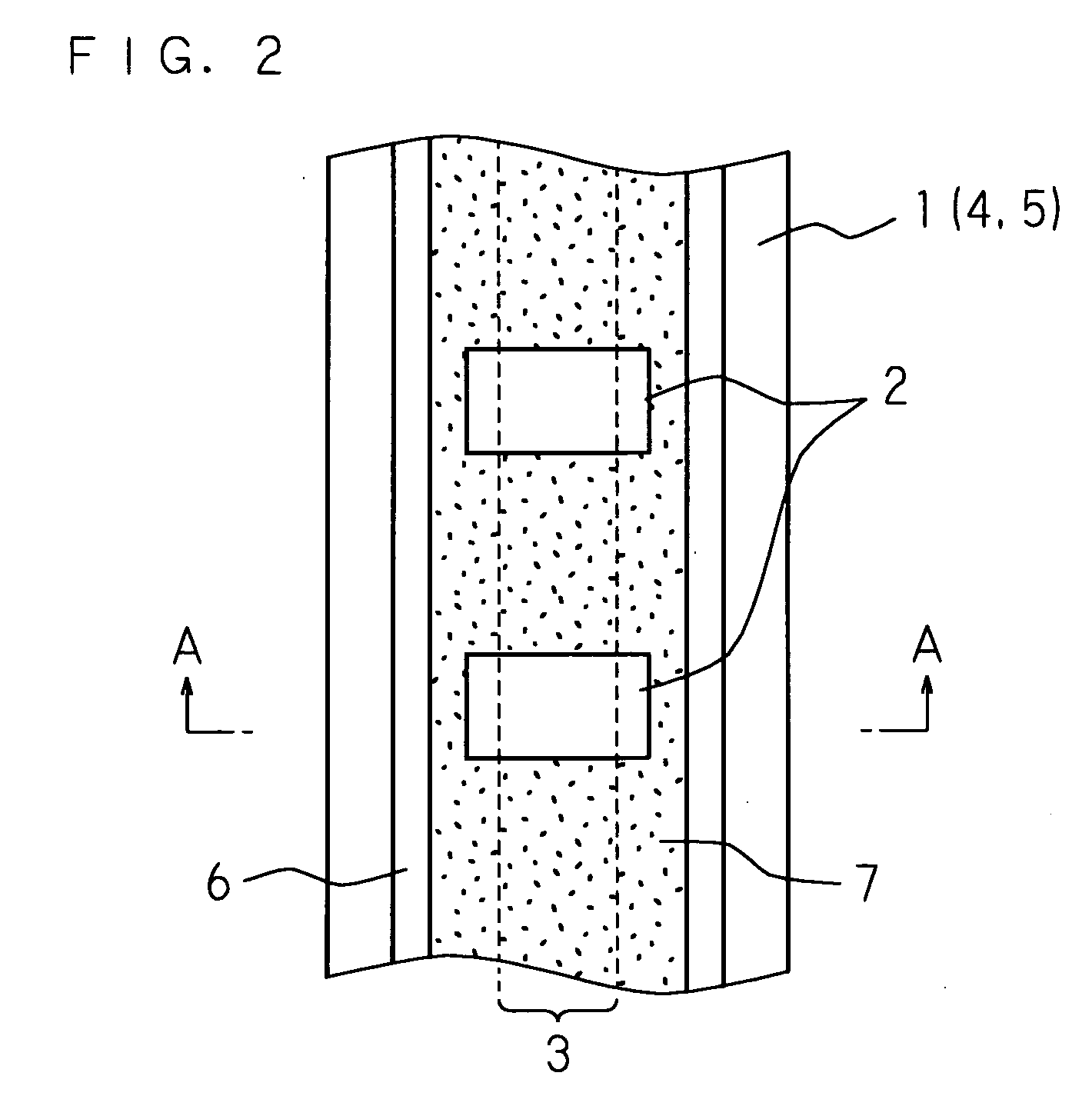
[0031]FIG. 1 is a schematic cross-sectional view of a light-emitting discharge tube according to a first embodiment of the present invention. FIG. 2 is a schematic plan view of the light-emitting discharge tube of FIG. 1 as viewed from its upper flat side. FIG. 1 is a cross-sectional view taken in the direction of arrow AA of FIG. 2.

[0032] A light-emitting discharge tube 10 has discharge electrodes 2 on a front side of an outer wall surface of a glass tube (tube body for a light-emitting discharge tube) 1 and an address electrode 3 on a back side thereof. The glass tube 1 has dimensions, for example, with a length of 300 mm or more, a tube outside diameter of 2 mm or less, and a tube wall thickness of 0.1 mm or less, and is formed of borosilicate glass or the like. The cross-section of the glass tube 1 is not limited to circular as shown in the drawing and may be in the shape of a flat ellipse. Inside the glass tube 1, a discharge gas, such as xenon (Xe) or neon (Ne), for example, ...

second embodiment

[0041]FIG. 4 is a schematic process flowchart of a method of fabricating a light-emitting discharge tube, according to a second embodiment of the present invention. First, a tubular base material is formed. The tubular base material is stretched (redrawn) to form a tube body (glass tube 1) for a light-emitting discharge tube. There are no flaws on a surface (outer wall) of the glass tube 1 just after formed. Thus, a protective film 4 is coated and formed on the outer wall surface of the glass tube 1 successively just after the glass tube 1 is formed (that is, before proceeding to another step). Since the protective film 4 is successively coated and formed on the outer wall surface of the glass tube 1 just after formed, the outer wall surface of the glass tube 1 can be protected from external forces in subsequent processes, ensuring surface protection.

[0042] In the present embodiment, as the protective film 4, an organic acid metal solution (organometallic compound solution) is coat...

third embodiment

[0047]FIG. 5 is a schematic process flowchart of a method of fabricating a light-emitting discharge tube, according to a third embodiment of the present invention. Basically, a light-emitting discharge tube 10 is formed through the same process as the second embodiment, and thus, a detailed description thereof is omitted. In the present embodiment, as a protective film 4, an organic acid metal solution (organometallic compound solution) is coated. For the organic acid metal solution, a material that becomes a conductive metal oxide film by calcination is used. Since the protective film 4 becomes a metal oxide film by calcination, a dense, stable metal oxide film with good film quality can be formed.

[0048] Thereafter, an electron emission film 5 is formed on an inner wall surface of a glass tube 1 on which the metal oxide film is formed by calcination. The coating method for the protective film 4 includes a method of allowing a tube to pass through a coating solution, a method that ...


PUM


Abstract

A light-emitting discharge tube in which an outer wall surface of a glass tube is made less susceptible to flaws by forming a protective film on the outer wall surface of the glass tube, a method of fabricating the light-emitting discharge tube, and a protective film forming apparatus are provided. The light-emitting discharge tube defines light-emitting discharge regions by a plurality of external electrodes. The outer wall surface of the light-emitting discharge tube (the glass tube) is coated with the protective film (a metal film, a conductive metal oxide film, an insulating metal oxide film, or an organic film).

Description

[0001] This application is a continuation of PCT International Application No. PCT / JP2003 / 013098 which has an International filing date of Oct. 10, 2003, which designated the United States of America.TECHNICAL FIELD [0002] The present invention relates to a light-emitting discharge tube, a method of fabricating the light-emitting discharge tube, and a protective film forming apparatus that forms a protective film on a surface of the light-emitting discharge tube. BACKGROUND ART [0003] A light-emitting discharge tube that causes a gas discharge to occur by the application of a voltage from external electrodes and emits light by a phosphor contained inside thereof is proposed for use in display devices (see Japanese Patent Application Laid-Open No. 2003-86141, for example). Such a light-emitting discharge tube uses a glass tube having, for example, a length of 300 mm or more, and an outside diameter of 2 mm or less, and a wall thickness of 0.1 mm or less. Since the length of the light...

Claims


Application Information

Patent Timeline
IPC IPC(8): H01J65/00H01J61/06H01J11/00H01J9/20H01J61/35H01J65/04
CPCH01J9/20H01J61/35H01J65/00H01J65/04H01J65/042H01J2209/015
Inventor YAMADA, HITOSHITOKAI, AKIRAISHIMOTO, MANABUYAMAZAKI, YOSUKEAWAMOTO, KENJISHINOHE, KOJIHIRAKAWA, HITOSHI
Owner SHINODA PLASMA
Why Eureka
Try Eureka