Adaptive equalizer circuit

a technology of equalizer circuit and equalizer, which is applied in the field of equalization method of signals, can solve the problems of inability to find appropriate, limit the range of tracking characteristic changes, and use given, and achieve the effect of reducing circuit size and high performan

Inactive Publication Date: 2006-08-10
FUJITSU LTD
View PDF2 Cites 21 Cited by
  • Summary
  • Abstract
  • Description
  • Claims
  • Application Information

AI Technical Summary

Benefits of technology

[0020] The present invention makes it possible to secure an adequate data amplitude enabling a data judgment if a characteristic of transmission line changes greatly, thereby providing an adaptive equalizer as a high performance equalizer. An execution of control operation for adaptive equalization every time an identity with a preset data pattern is detected makes it possible to reduce a circuit size.

Problems solved by technology

The conventional configuration shown by FIG. 4, however, has been faced with the problem that there is a limitation in a range of tracking the characteristic changes due to temperature and / or secular changes of a transmission line because the content of the matrix, as the matrix reflecting the characteristics of transmission line and respective filters constituting the equalizer circuit, is fixed.
Particularly, if a characteristic of transmission line changes greatly, a use of given matrix will no longer be able to find appropriate values of the coefficients A0, A1 and A2 of the respective filters constituting the equalizer circuit.
Such has been a problem.
A preparation of such a plurality of matrices and a grasp of tracking ranges for the characteristic of the transmission line for each matrix demand a series of works in need of vast amount of man-hours, hence becoming a large obstacle in an actual operation of an equalizer circuit.
Such has been the problem.

Method used


Image

  • Adaptive equalizer circuit
  • Adaptive equalizer circuit
  • Adaptive equalizer circuit

Examples


first embodiment

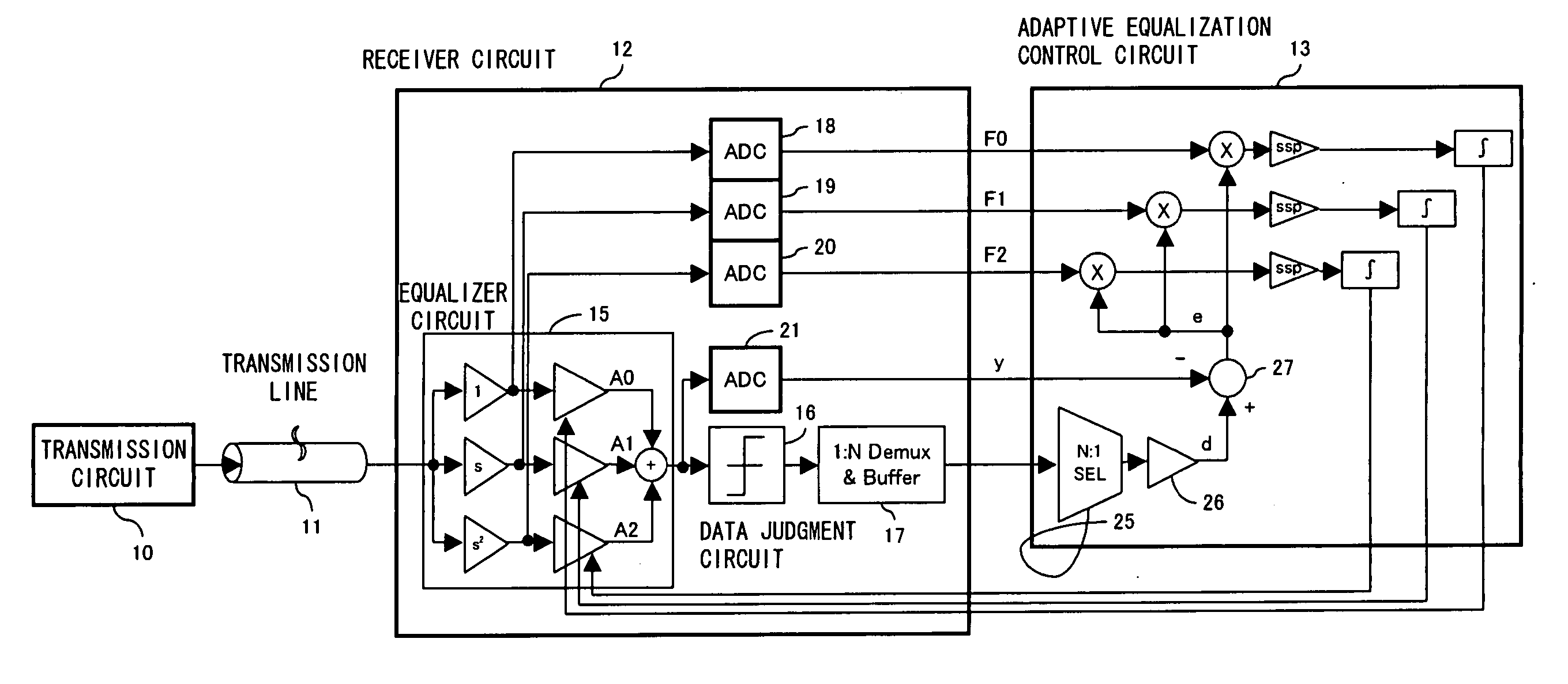
[0045]FIG. 8 describes an adaptive equalization method of a first embodiment according to the present invention. As with the conventional configuration shown by FIG. 4, a transmitted data transmitted from a transmission circuit 10 by way of a transmission line 11 is received by a receiver circuit 12. An adaptive equalization control circuit 13 for adaptively controlling an equalizer circuit 15 with in the receiver circuit controls the filter coefficients A0, A1 and A2 of respective filters within the equalizer circuit 15 adaptively.

[0046] In the inside of receiver circuit 12, a data judgment unit 16, given an output of the equalizer circuit 15, judges a ±1 of data so as to give the judgment result to the adaptive equalization control circuit 13 by way of a de-multiplexer & buffer 17. And input values for respective nodes within the equalizer circuit 15, that is, for the input terminals of gain amplifiers for respective filters are given to the adaptive equalization control circuit 1...

second embodiment

[0055] In the second embodiment, the configuration is such that a result of judging an output of the equalizer circuit 15 by the data judgment unit 16 is compared with a preset data pattern, e.g., “0001”; the selector 30 is switched at the time of the preset data pattern being detected within the N-bit output from the de-multiplexer & buffer 17 as a judgment result, the output result of the selector 30 is converted to a digital data by the AD converter 31; and the values F0, F1, F2 and y will be held in the aforementioned order from the top by the hold circuit 33.

[0056] Here, the description is about setting a data pattern such as “0001”. It is possible to consider an influence of past events as the characteristic of the transmission line 11, that is, how much the influence of data transmitted in the past still remains as a measure of characteristic. In other words, it is beneficial to look at some bits of past data to see whether an influence of the past data still remains or not. ...

third embodiment

[0067] To that end, the third embodiment furnishes with three registers 45, 46 and 47 for providing the adaptive equalization control circuit 13 with a signal value of internal nodes of the equalizer circuit 15, that is, input values to the gain amplifiers for the respective filters; a comparator 48 for comparing between a preset data pattern within the adaptive equalization control circuit 13, e.g., “0001”, and an output of the de-multiplexer & buffer 17; and a selector 49 for outputting a result of the subtracter 27 subtracting an output y of the equalizer circuit 15, which is outputted from the AD converter 21, from the predicted amplitude d as an amplitude error e when the value of the DET signal outputted from the comparator 48 is “1” and for outputting “0” as the amplitude error e when the value of the DET signal is “0”.

[0068] Here, the values of F0, F1 and F2 stored in the registers 45, 46 and 47, respectively, are amplitude values inputted to the gain amplifiers for the resp...


PUM


Abstract

An adaptive equalizer circuit equipped by a control unit for controlling an equalizer circuit, comprising a detection unit for detecting an identity of a preset data pattern with a data pattern as a result of data judgment for an output of the equalizer circuit, a monitor unit for sequentially monitoring an input to a gain amplifier for each of a plurality of filters constituting the equalizer circuit and an output thereof every time the identity detection unit detects an identity, and a unit for making the control unit operate an adaptive equalization control by providing the control unit with the monitoring result, thereby making it possible to track a great change in a characteristic of transmission line without using a matrix responding to the characteristic of the transmission line or a convolution operation by using the matrix.

Description

CROSS-REFERENCE TO RELATED APPLICATIONS [0001] This application is based upon and claims the benefit of priority from the prior Japanese Patent Application No. 2005-035171 filed on Feb. 10, 2005, the entire contents of which are incorporated herein by reference. BACKGROUND OF THE INVENTION [0002] 1. Field of the Invention [0003] The present invention relates to an equalization method for a signal such as communication data, in particular to an adaptive equalization method for a data receiver circuit engaged in a data exchange between boards or chassis mounted with LSI for example and to an adaptive equalizer circuit for reducing a distortion of received data influenced by a transmission distortion, or a disturbance, occurring in a transmission path. [0004] 2. Description of the Related Art [0005] When transmitting and receiving data by way of a transmission line with a large loss, an equalizer circuit is generally used at a receiving end in order to compensate for the loss. FIG. 1 d...

Claims


Application Information

Patent Timeline
Patent Type & Authority Applications(United States)
IPC IPC(8): H03K5/159
CPCH04L25/03885H04L2025/03681H04L2025/03789
Inventor YAMAGUCHI, HISAKATSU
Owner FUJITSU LTD
Why Eureka
Try Eureka