Laminated ceramic capacitor

a technology of laminated ceramic capacitors and capacitors, which is applied in the direction of fixed capacitors, natural mineral layered products, solid-state devices, etc., can solve the problems of difficult delamination between internal electrodes and dielectric layers, and the dielectric layer tends to deformation, and achieves superior electrostatic capacitance and high insulation resistan

Active Publication Date: 2006-08-10
TDK CORPARATION
View PDF7 Cites 8 Cited by
  • Summary
  • Abstract
  • Description
  • Claims
  • Application Information

AI Technical Summary

Benefits of technology

[0017] Also, the ceramic material is preferably a complex oxide having Ba and Ti as its principal ingredients. In t

Problems solved by technology

However, when the dielectric layer in the laminated ceramic capacitor is made thinner, if the number of laminated layers increases, a deformation tends to arise in the dielectric layer.
As a result, in the laminated ce

Method used


Image

  • Laminated ceramic capacitor
  • Laminated ceramic capacitor
  • Laminated ceramic capacitor

Examples


Embodiment Construction

[0021] Hereafter, one aspect of the invention will be described referring to the drawings. In the drawings, the same elements are assigned identical symbols, and their description will not repeated.

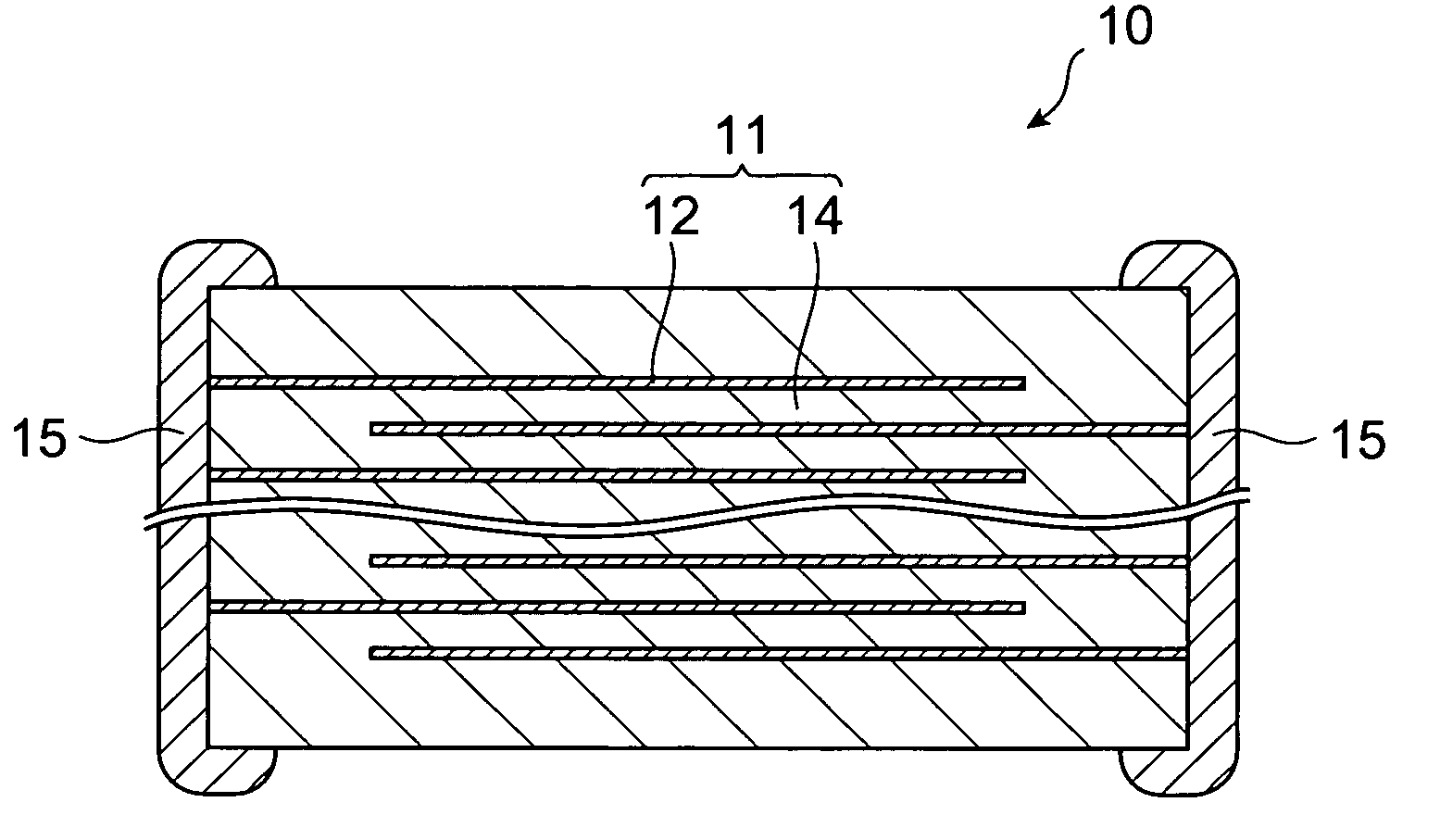
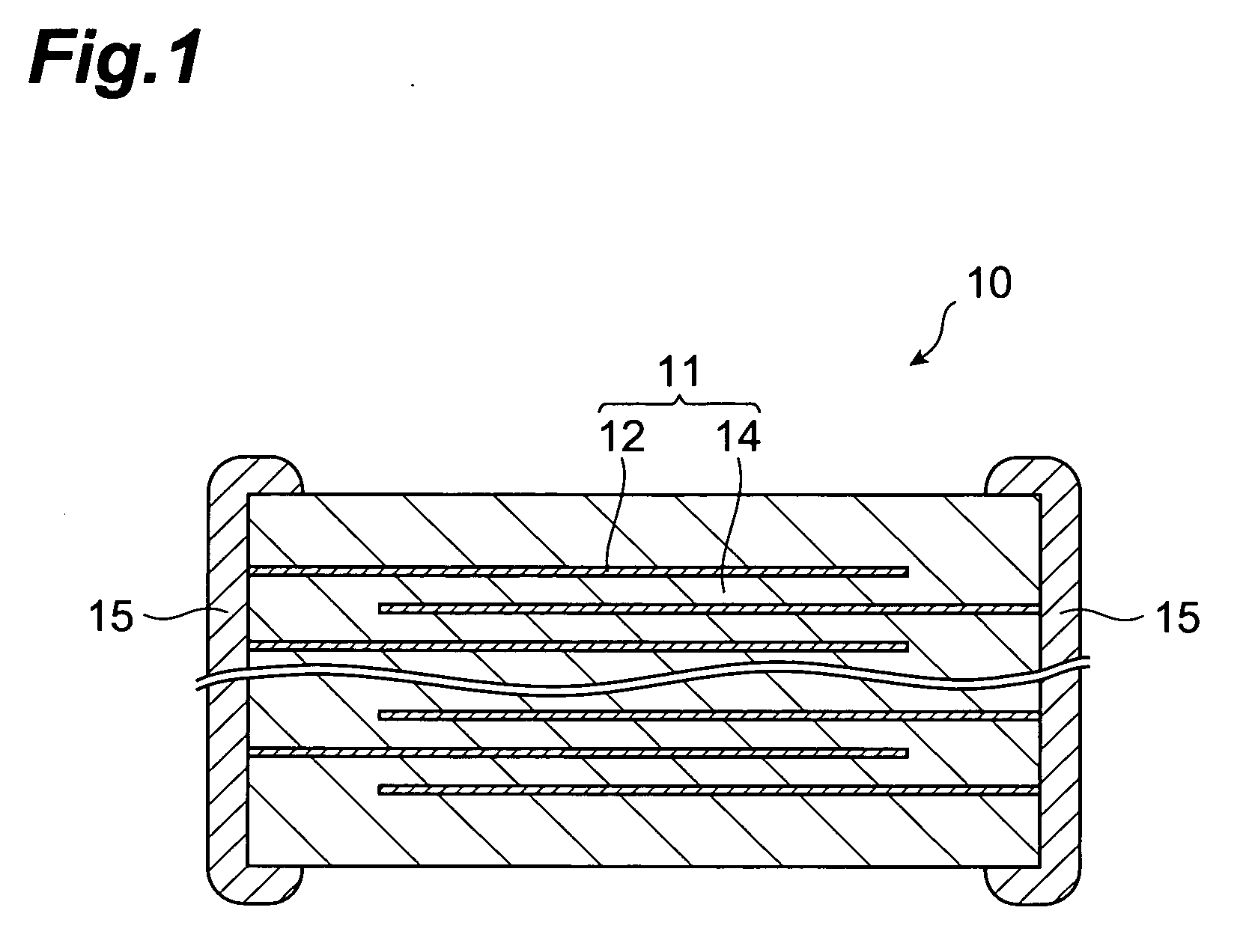
[0022]FIG. 1 is a drawing schematically showing a cross-section of a laminated ceramic capacitor according to this aspect. A capacitor 10 (laminated capacitor) comprises a rectangular parallelepiped-shaped capacitor body 11 wherein internal electrodes 12 and a dielectric layer 14 are alternately laminated, external electrodes 15 being respectively provided on opposite end faces of this capacitor body 11.

[0023] In this capacitor 10, the internal electrodes 12 are formed so that one end of the internal electrode 12 is exposed on the end face of the capacitor body 11, and the internal electrodes 12 are laminated so that the ends thereof is alternately exposed on the opposite end face of the capacitor body 11. The component materials of the internal electrodes 12 are not particularly limite...


PUM

PropertyMeasurementUnit
Thicknessaaaaaaaaaa

Abstract

The capacitor 10 (laminated ceramic capacitor) of the invention comprises a capacitor body 11 wherein internal electrodes 12 (electrodes) and a dielectric layer 14 are alternately laminated, and external electrodes 15 are provided on the end faces thereof. The dielectric layer 14 has a site containing particles of a dielectric material which is formed of only one of these particles in its thickness direction. Regions 24 comprising at least one element selected from a group comprising Si, Li and B are scattered between the internal electrodes 12 and dielectric layer 14.

Description

BACKGROUND OF THE INVENTION [0001] 1. Field of the Invention [0002] The present invention relates to a laminated ceramic capacitor. [0003] 2. Related Background of the Invention [0004] A laminated ceramic capacitor generally has a structure wherein a dielectric layer of a ceramic material and an internal electrode are laminated alternately. In recent years, a demand has emerged for a small laminated ceramic capacitor having a large electrostatic capacitance. In order to satisfy this demand, in laminated ceramic capacitors, the dielectric layer is being made thinner, and the number of laminated layers is increasing. [0005] In one example of such a laminated ceramic capacitor known in the art, the dielectric layer has a structure formed only of single ceramic material particles, i.e., a one layer-one particle structure (e.g., JP-B No. 3370933). SUMMARY OF THE INVENTION [0006] However, when the dielectric layer in the laminated ceramic capacitor is made thinner, if the number of lamina...

Claims


Application Information

Patent Timeline
IPC IPC(8): B32B15/04B32B9/00B32B19/00
CPCB32B2311/22C04B35/4682C04B35/49C04B35/6262C04B2235/3203C04B2235/3208C04B2235/3213C04B2235/3215C04B2235/3225C04B2235/3239C04B2235/3244C04B2235/3262C04B2235/3279C04B2235/3409C04B2235/3418C04B2235/6582C04B2235/85C04B2237/346C04B2237/405H01G4/30
Inventor IWANAGA, DAISUKE
Owner TDK CORPARATION
Why Eureka
Try Eureka