
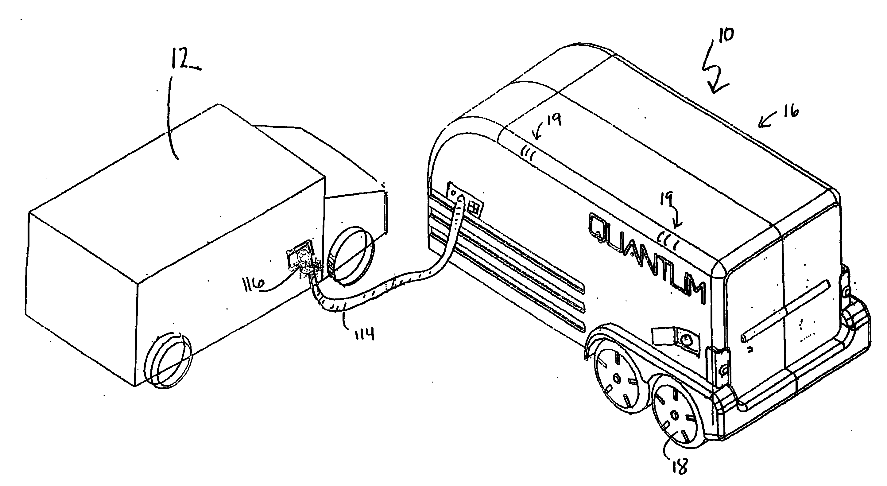
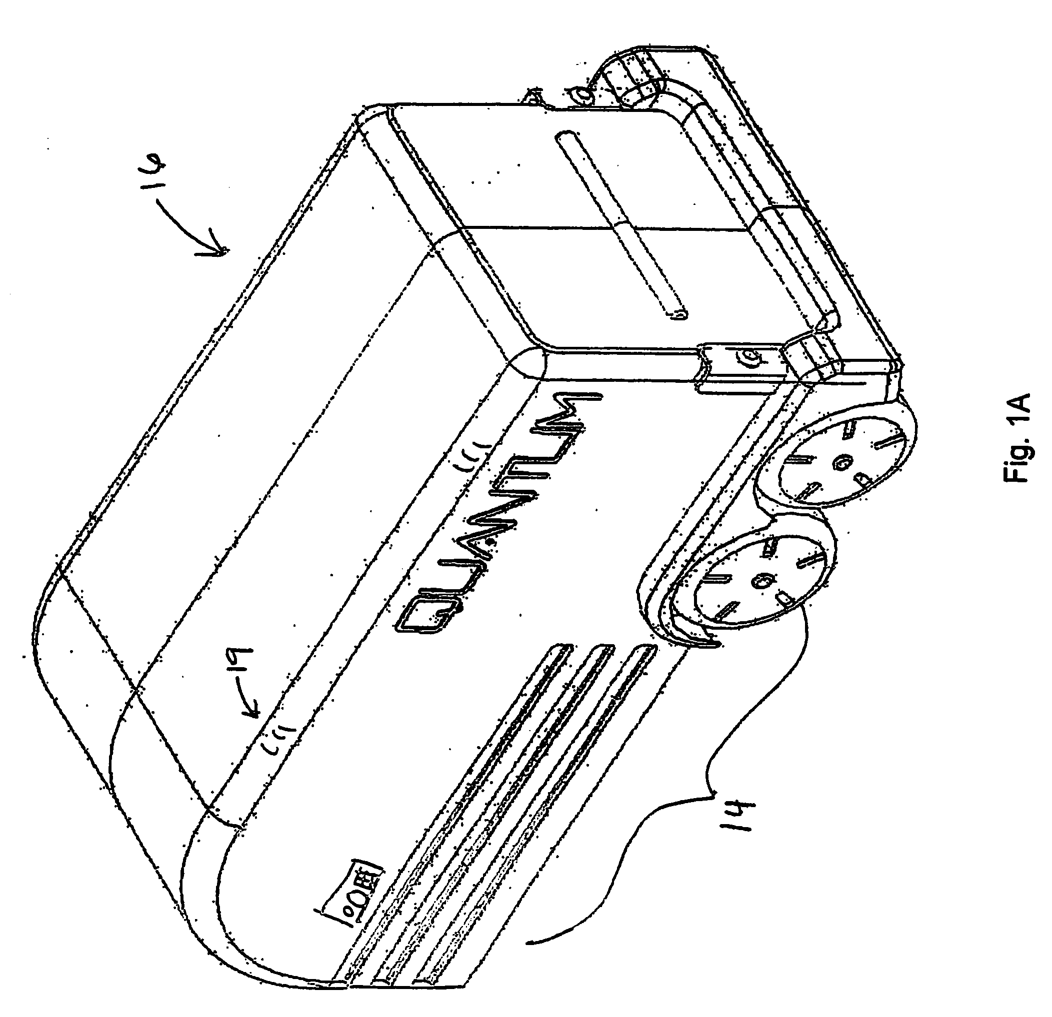
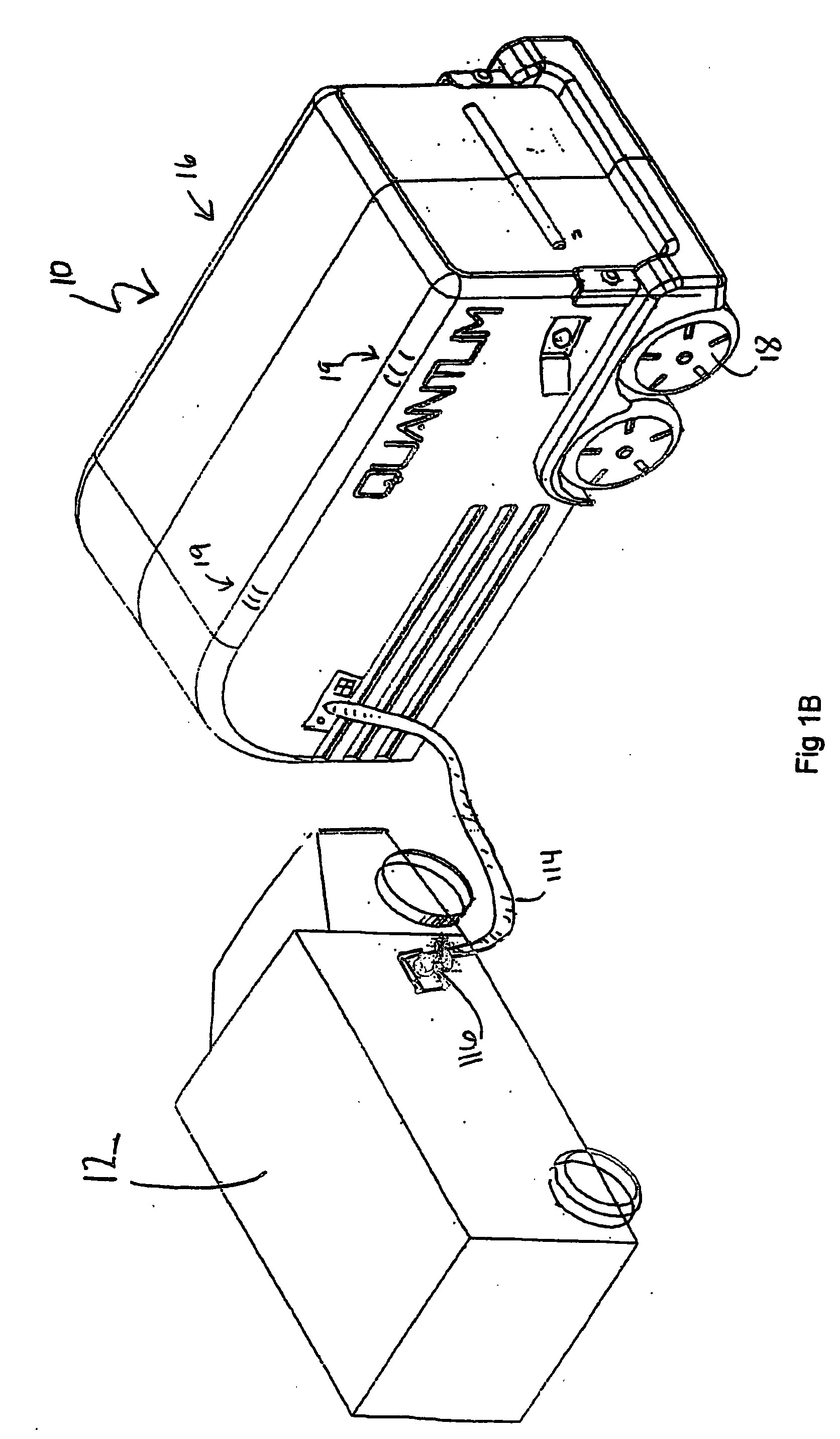
Transportable hydrogen refueling station

a hydrogen refueling station and transportable technology, applied in the direction of liquid handling, container discharging methods, packaged goods types, etc., can solve the problem of mismeasurement, achieve the effect of reducing facilitating leakage monitoring, and increasing the density of hydrogen gas

Inactive Publication Date: 2006-08-17
QUANTUM FUEL SYST TECH WORLDWIDE INC
View PDF14 Cites 38 Cited by
  • Summary
  • Abstract
  • Description
  • Claims
  • Application Information

AI Technical Summary

Benefits of technology

The solution provides a lightweight, safe, and efficient hydrogen refueling system with increased energy density, meeting user convenience expectations by optimizing hydrogen density and refueling time, while minimizing the risks associated with hydrogen-oxygen mixtures.

Problems solved by technology

The energy density of a system for transporting hydrogen could be measured as grams / liter of stored gas as done by Ovshinsky in the U.S. Pat. No. 6,305,442 patent, however, such a measurement can be misleading when transportability of the hydrogen is a factor.

Method used


Image

  • Transportable hydrogen refueling station
  • Transportable hydrogen refueling station
  • Transportable hydrogen refueling station

Examples


example 1

[0047] If the external hydrogen feed gas is supplied to the hydrogen storage subsystem 30 at approximately 1,000 psi then the first compressor subsystem 50 can increase the pressure of the hydrogen gas by up to about four times which would be as high as approximately 4,000 psi. However, if the desired storage is about 10,000 psi then the gaseous hydrogen is directed by the actions of the system controller 400 (i.e. opening and closing valves) from the first compressor subsystem 50 to the second intensifier subsystem 80.

[0048] The pressure of gaseous hydrogen which enters the second compressor subsystem 80 at about 4,000 psi can be increased to achieve the desired 10,000 psi. As an additional fail safe, manual control valves 98 and 98′ may be affixed to each of the lightweight composite hydrogen storage tanks 100 and 100′ to physically prevent the flow of hydrogen gas in or out of the lightweight composite hydrogen storage tanks 100 and 100′.

[0049] The system controller 400 can be ...

example 2

[0050] If the external hydrogen feed gas is supplied to the hydrogen storage subsystem 30 at approximately 3,300 psi then the first compressor subsystem 50 can increase the pressure of the hydrogen gas by up to about four times which would be as high as approximately 9,900 psi. Accordingly, if the desired storage pressure of the hydrogen gas in the lightweight hydrogen storage vessels is about 10,000 psi the second compressor subsystem can be by-passed by keeping the inlet check valve 82 closed and directing the hydrogen gas to the by-pass inlet / outlet control valve 96.

Self-Filling Refueling Station

[0051] In another embodiment shown in FIGS. 5A and 5B a hydrogen producing subsystem 500 is part of the hydrogen storage subsystem 30. The hydrogen producing subsystem 500, in this embodiment, is comprised of a KOH electrolyzer module 502 and a cooling module 504. One suitable KOH electrolyzer is a IMET electrolyzer manufactured by Vandenborre Hydrogen Systems. The cooling module 504 sh...


PUM

PropertyMeasurementUnit
burst pressure ratingaaaaaaaaaa
weightaaaaaaaaaa
weightaaaaaaaaaa

Abstract

A portable hydrogen refueling stations which can dispense gaseous hydrogen from one or more internal high pressure tanks. The refueling station can be refilled with a lower pressure hydrogen gas feed and then compressed for storage within a refueling station.

Description

FIELD OF THE INVENTION [0001] This invention relates to a rechargeable device for storing and, when desired, releasing hydrogen. Among other applications, the device can be used in the energy generation or transportation industries. BACKGROUND OF THE INVENTION [0002] A hydrogen economy has become a National vision. “Hydrogen has the potential to solve two major energy challenges that confront America today: reducing dependence on petroleum imports and reducing pollution and greenhouse gas emissions. There is general agreement that hydrogen could play an increasingly important role in America's energy future. Hydrogen is an energy carrier that provides a future solution for America.”A National Vision of America's Transition to a Hydrogen Economy to 2030 and Beyond, based on results of the National Hydrogen Vision Meeting, Washington, D.C., Nov. 15-16, 2001 United States Department of Energy February 2002. [0003] For mobile hydrogen powered systems, i.e., fuel cell powered electric ve...

Claims


Application Information

Patent Timeline
Patent Type & Authority Applications(United States)
IPC IPC(8): B65B1/04B60P3/14B60P3/22B60P3/24
CPCB60P3/14F17C2270/0168B60P3/24B60S5/02F17C5/007F17C7/02F17C2221/012F17C2223/0153Y02E60/321F17C2201/0109F17C2201/035F17C2201/056F17C2205/0107F17C2205/0111F17C2205/0134F17C2205/0157F17C2205/0176F17C2205/0329F17C2205/0332F17C2205/0335F17C2221/016F17C2223/0123F17C2223/036F17C2227/0157F17C2227/0337F17C2227/04F17C2227/044F17C2250/043F17C2250/0439F17C2250/0636F17C2260/042F17C2265/066B60P3/2245Y02P90/45Y02E60/32Y02E60/50Y02E60/36
Inventor NIEDZWIECHI, ALANABELE, ANDY
Owner QUANTUM FUEL SYST TECH WORLDWIDE INC
Learn More