Magnetic assembly for a linear beam tube

a technology of linear beam tube and magnetic assembly, which is applied in the direction of discharge tube/lamp details, magnetic discharge control, transit tube circuit elements, etc., can solve the problems of different constraints in assembly or disassembly of the device, density modulation of electron beam,

Inactive Publication Date: 2006-08-17
E2V TECH (UK) LTD
View PDF4 Cites 0 Cited by
  • Summary
  • Abstract
  • Description
  • Claims
  • Application Information

AI Technical Summary

Problems solved by technology

This causes density modulation of the electron beam.
However, such integral designs place different constraints in terms of assembly or disassembly of the device due to the fact that components such as a fixed output are unable to pass other components such as parts of the magnetic circuit.

Method used


Image

  • Magnetic assembly for a linear beam tube
  • Magnetic assembly for a linear beam tube
  • Magnetic assembly for a linear beam tube

Examples


Embodiment Construction

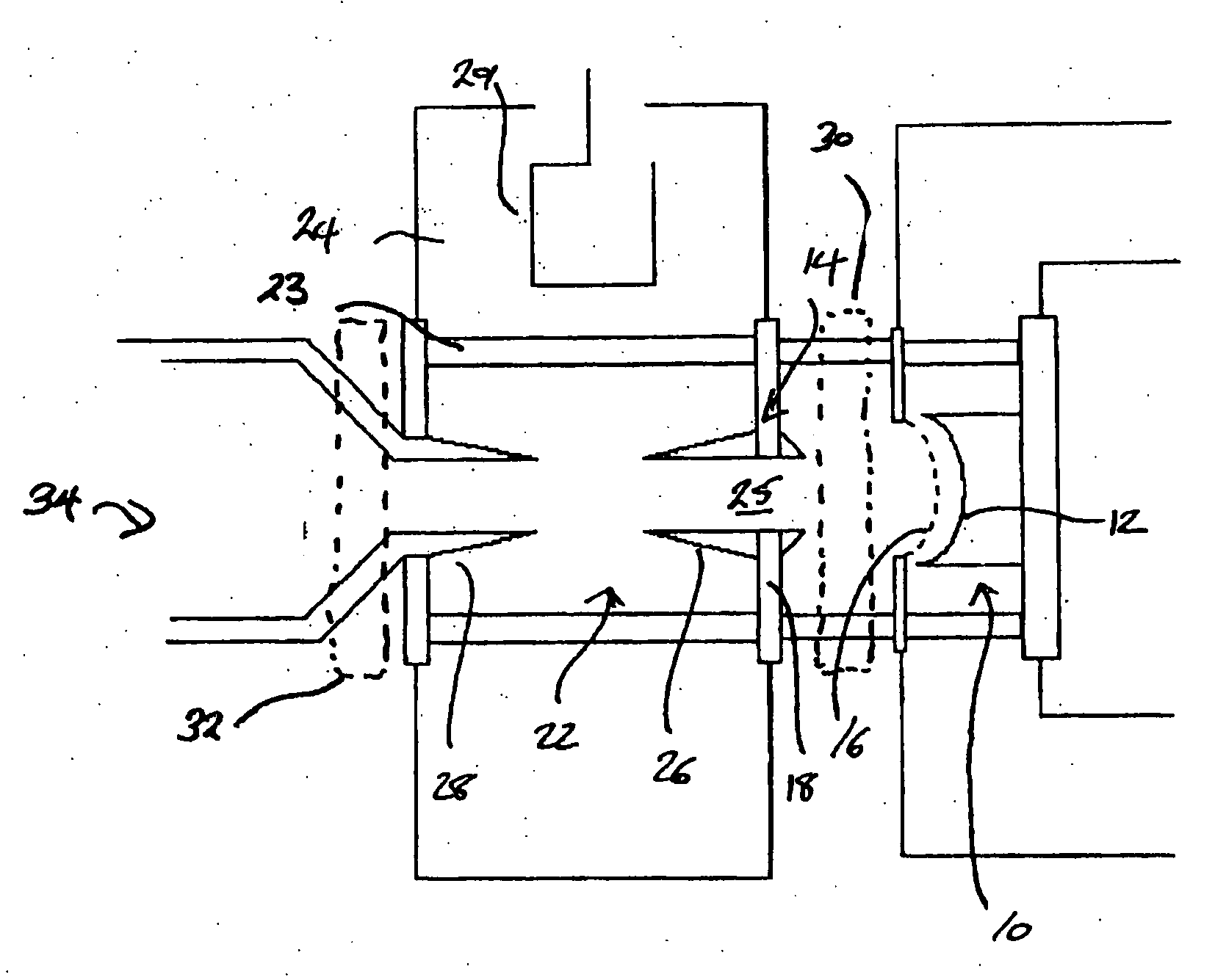
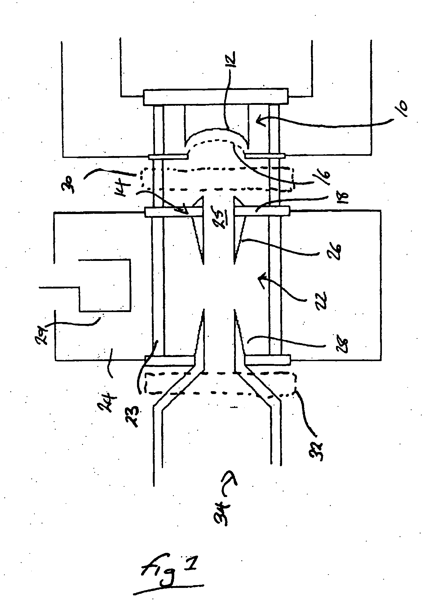
[0022] The embodiment of the invention described is an Inductive Output Tube (IOT). However, it would be appreciated to the skilled person that the invention applies equally to other linear beam devices such as travelling wave tubes and Klystrons.

[0023] The embodiment of the present invention addresses the problems associated with the installation or removal of linear beam tubes containing integral output cavities and feeders, (or sidearms), from their associated circuit assemblies. This is achieved by pivoting those parts of the circuit assembly that would otherwise foul on the tube feeder out of the path of the tube for the duration of the installation or removal process.

[0024] The embodiment of the present invention avoids the possible need to break electrical connections, and makes tube installation / extraction a one man process while also ensuring that the magnetic axis and precision of the magnetic frame is not compromised by the complete removal of major components.

[0025] A...


PUM


Abstract

An electron beam tube device has a magnetic frame with the top part being pivotable so as to pivot from a closed position in which the top part, including an electromagnetic coil covers the electron beam tube to an open position in which the electron beam tube is uncovered. This allows electron beam tubes with either large parts or integral parts such as output feeders to be removed from the magnetic frame without complete removal of the top plate.

Description

CROSS-REFERENCE TO RELATED APPLICATION [0001] This application claims the priority of British Patent Application No. 0502921.0 filed on Feb. 11, 2005, the subject matter of which is incorporated herein by reference. BACKGROUND OF THE INVENTION [0002] The present invention relates to a magnetic assembly for linear beam tube devices, in particular, for electron beam tube devices such as those known as Inductive Output Tubes (IOTs).[0003] Linear beam tube devices such as electron beam tube devices are used for the amplification of RF signals. There are various types of linear electron beam tube device known to those skilled in the art, two examples of which are the klystron and the Inductive Output Tube (IOT). Linear electron beam tubes incorporate an electron gun for the generation of an electron beam of an appropriate power. The electron gun includes a cathode heated to a high temperature so that the application of an electric field between the cathode and an anode results in the emi...

Claims


Application Information

Patent Timeline
Patent Type & Authority Applications(United States)
IPC IPC(8): H01J1/50H01J23/10H01J23/087
CPCH01J23/087H01J23/10H01J25/04H05H7/04
Inventor ANDREWS, STUART WILLIAM
Owner E2V TECH (UK) LTD
Why Eureka
Try Eureka