Heat sink and heat sink assembly

a technology of heat sink and heat sink assembly, which is applied in the direction of indirect heat exchangers, electrical apparatus construction details, lighting and heating apparatus, etc., can solve the problems of limiting the effectiveness of any increase in heat sink surface area, and reducing the overall system size and cost. , to achieve the effect of dissipating large amounts of power

Inactive Publication Date: 2006-08-17
KILEY RICHARD F +1
View PDF11 Cites 47 Cited by
  • Summary
  • Abstract
  • Description
  • Claims
  • Application Information

AI Technical Summary

Benefits of technology

[0023] It is a still further aspect of the present invention to provide a heat sink capable of reducing overall system size and costs from those currently available.
[0024] It is a still further aspect of the present invention to provide a heat sink assembly that does not require active liquid cooling to dissipate large amounts of power from a heat generating component or device.

Problems solved by technology

As technology has advanced, the amount of heat to be dissipated from many of these components has risen dramatically, while the acceptable cost of heat dissipating devices has remained constant or, in many cases, has dropped.
However, in many applications, other factors come into play that can limit the effectiveness of any increase in heat sink surface area.
One common limiting factor is the amount of heat that may be conducted through the fins themselves.
Conduction losses occur because solid materials are not perfect conductors of heat.
This causes a significant reduction in the efficiency of the heat sink and effectively eliminates any advantage to adding surface area by lengthening fins.

Method used


Image

  • Heat sink and heat sink assembly
  • Heat sink and heat sink assembly
  • Heat sink and heat sink assembly

Examples


Embodiment Construction

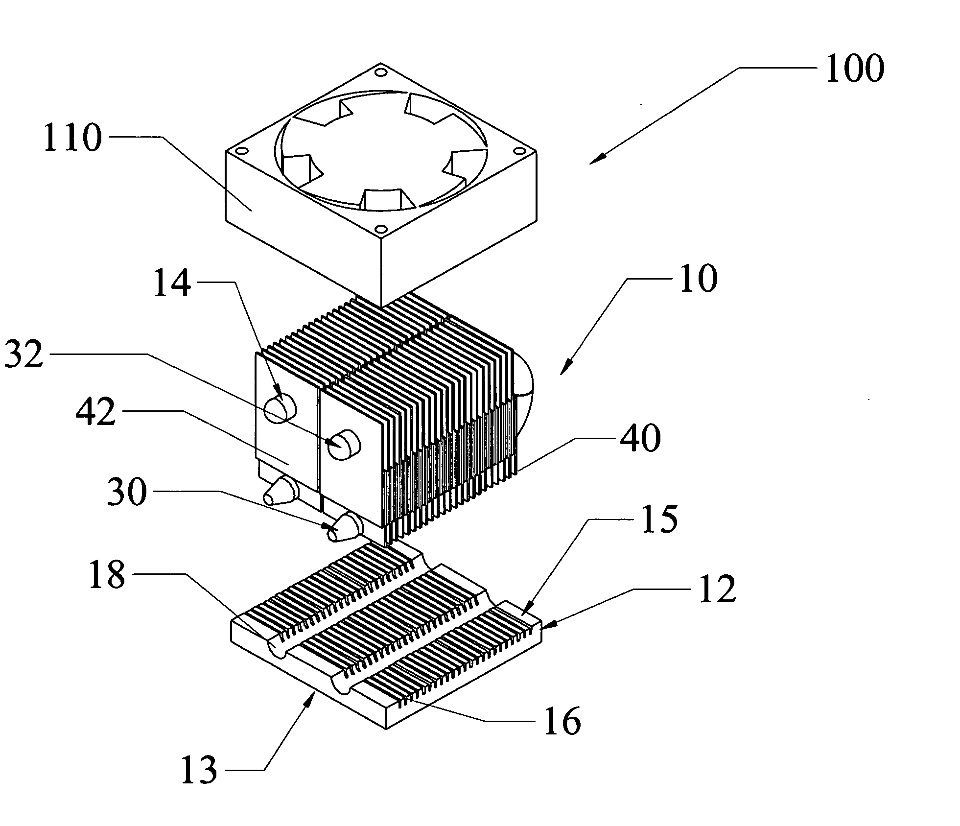
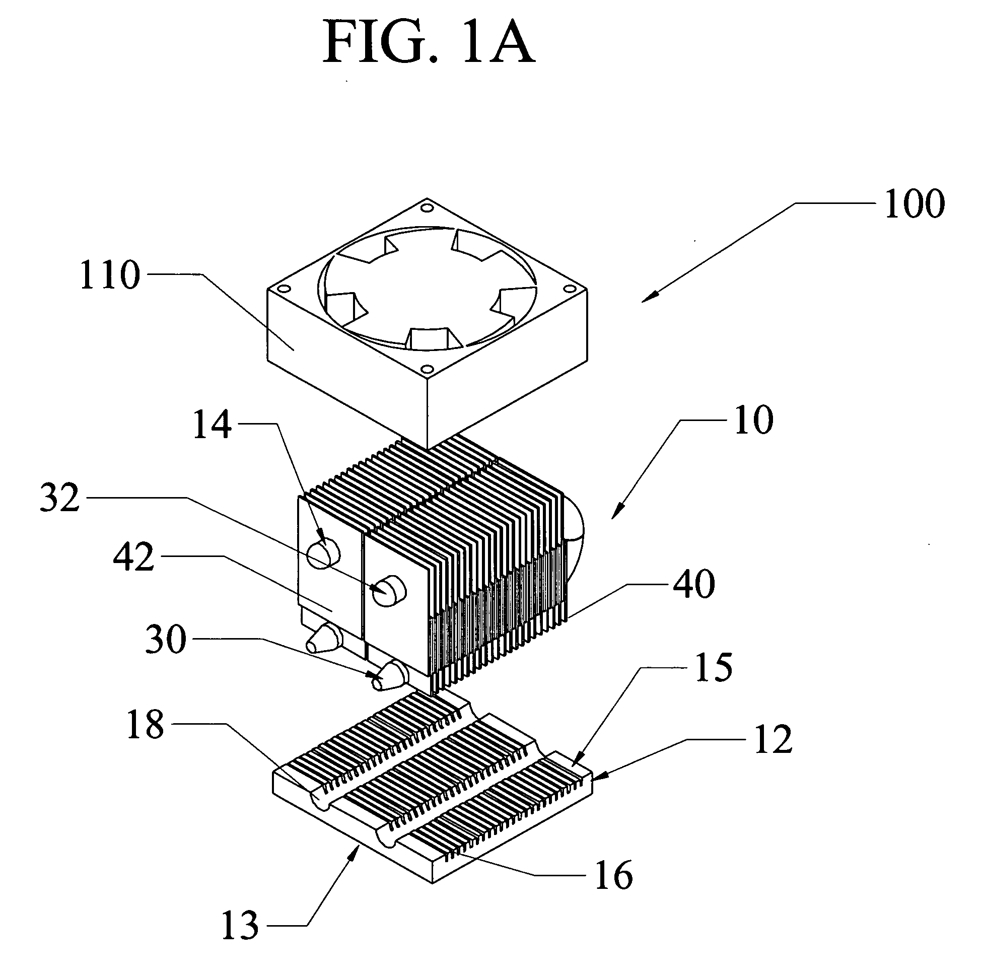
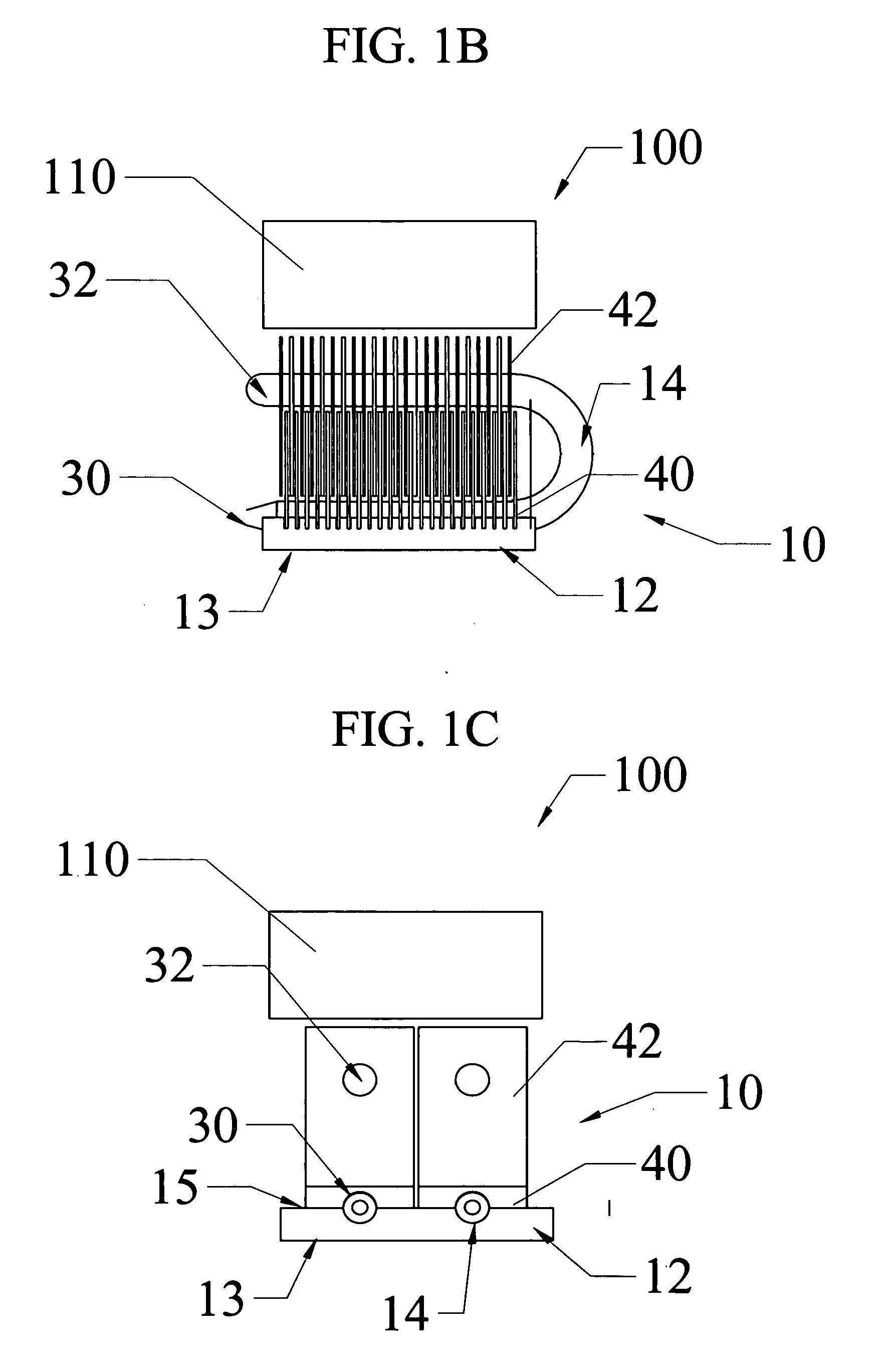
[0039] Referring first to FIGS. 1A-1C, one embodiment of the heat sink assembly 100 of the present invention is shown. The heat sink assembly 100 includes a heat sink 10 and a fan 110. The heat sink includes a base plate 12, a first plurality of convective surfaces, shown here as fins40, a pair of heat pipes 14, and a second plurality of convective surfaces 42, shown here as fins 42.

[0040] The top surface 15 of the base plate 12 includes a plurality of slots 16, into which the first plurality of fins 40, are attached, and a pair of channels 18, into which the evaporator portions 30 of a pair of heat pipes 14 are attached. The base plate 12 has a bottom surface 13 that is dimensioned and shaped to promote good thermal contact with the heat source (not shown). The base plate 12 is manufactured of a material, such as copper or aluminum, that has relatively good thermal conductivity, and should be of sufficient thickness to efficiently spread the heat from a heat source (not shown) dis...


PUM


Abstract

A heat sink and a heat sink assembly that includes the heat sink and a source of flowing air, such as a fan. The heat sink includes a base from which a first plurality of convective surfaces extends. At least one heat pipe is in thermal contact with the base and extends therefrom. The heat pipe includes an evaporator portion in thermal contact with the base and a condenser portion. A second plurality of convective surfaces is in thermal communication with the condenser portion of the heat pipe.

Description

CLAIM OF PRIORITY [0001] This patent application claims the benefit of priority of U.S. Provisional Patent Application Ser. No. 60 / 652,997, filed on Feb. 14, 2005.FIELD OF THE INVENTION [0002] The present invention relates to the field of thermal management devices and, in particular, to heat sinks for convectively cooling electrical devices and components, and to assemblies utilizing these heat sinks. BACKGROUND OF THE INVENTION [0003] Semiconductors and other electrical components generate heat as a by-product of their operation. As technology has advanced, the amount of heat to be dissipated from many of these components has risen dramatically, while the acceptable cost of heat dissipating devices has remained constant or, in many cases, has dropped. Consequently, the art of heat sinking to cool heat-dissipating components has continually evolved to meet these new market requirements. [0004] Forced air convective heat sink assemblies are common in the industry and are preferred d...

Claims


Application Information

Patent Timeline
Patent Type & Authority Applications(United States)
IPC IPC(8): H05K7/20
CPCH01L23/427H01L23/467H01L2924/0002H01L2924/00F28D15/0275F28F1/32
Inventor KILEY, RICHARD F.BUSH, SIMONE
Owner KILEY RICHARD F
Why Eureka
Try Eureka