
Method and apparatus for recognizing location of a home device using RFID

a technology of home devices and location recognition, applied in the field of home networks, can solve the problems of reducing the effective range of home devices operated by simple controls, reducing security, and reducing the ability of home devices to load upnp middleware, so as to reduce the influence of contamination and environment, prevent friction and damage, and save time

Inactive Publication Date: 2006-08-24
SAMSUNG ELECTRONICS CO LTD
View PDF27 Cites 41 Cited by
  • Summary
  • Abstract
  • Description
  • Claims
  • Application Information

AI Technical Summary

Benefits of technology

[0012] It is another aspect of the invention to correctly recognize the locations of the home devices in the home without adding loads to the home devices for performing simple control operations.
[0018] In comparison with a contact card, RFID does not require a user to waste time inserting an RFID tag into an RFID reader, prevents friction and damage due to the mechanical contact, and reduces influences of contamination and environment. The RFID reader continuously generates radio waves, while the RFID tag transmits an identifier and data to the RFID reader when the RFID tag approaches an effective range of the radio waves generated from the RFID reader. The RFID reader transmits the data received from the RFID tag to a server, which then compares the data stored into the database with the data received from the RFID reader and provides necessary services. At this time, in the signal transmission and reception processes, signals corresponding to a frequency band of 10 kHz to 300 GHz are used, and the low frequency of 134.2 kHz is mainly used. Hereinafter, properties of the RFID will be described in detail.
[0019] An RFID system saves time since it simultaneously recognizes a plurality of RFID tags. Thus, RFID is replacing the bar code or the magnetic tag in the field of physical distribution because of the first feature. Further, RFID also is easily applicable according to system properties and environmental conditions and can widen the applicable field. Thus, the RFID tag is replacing a contact smart card used in the conventional parking control system. Further, RFID systems also have a long lifetime since they has a prominent environment-resistant property. Thus, RFID has a low error rate under unfavorable conditions such as when the RFID tag is damaged due to friction, dust, moisture, temperature, snow, rain, and etc. since the user doesn't have to insert the RFID tag into the RFID reader and the RFID is not in mechanical contact. Accordingly, RFID is mainly applied to a systems in open space. Still further, RFID is able to pass through nonmetallic materials. Still further, RFID is able to recognize a moving body with high speed by a recognition method. Thus, RFID can be used in an unmanned parking management system or an automatic fare collection system of an expressway or a tunnel since the RFID reader can recognize the RFID tag within 0.01 to 0.1 second.

Problems solved by technology

On the other hand, the wireless technique has weak points such as a chance of transmission errors due to interference and attenuation of the same frequency, a problem of security, etc.
The infrared ray method has the benefit that it can prevent radio wave interference, but has a weak point that its effective range is reduced.
In comparison with the infrared ray method, the radio wave method has a benefit of a wider effective range, but has a weak point that security is reduced.
In addition, a home device operated by simple controls cannot load Universal Plug and Play (UPnP) middleware since the load due to the UPnP middleware is added to a CPU and a software of the home device.
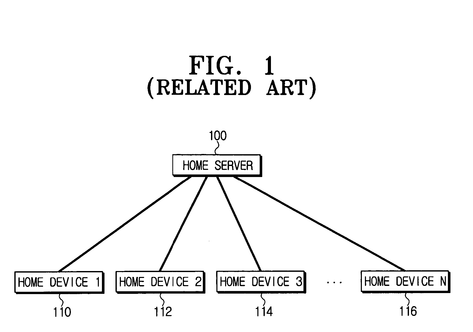
Still further, in a case of the home device on which the middleware is loaded, the home server 100 can recognize the operation of the home device connected to the home network, but cannot recognize the location of the home device in the home.
Furthermore, the home server 100 cannot recognize the location of the home device within the home network if the home device does not have the communication function.

Method used


Image

  • Method and apparatus for recognizing location of a home device using RFID
  • Method and apparatus for recognizing location of a home device using RFID
  • Method and apparatus for recognizing location of a home device using RFID

Examples


Embodiment Construction

[0027] Exemplary embodiments of the invention will now be described below by reference to the attached Figures. The described exemplary embodiments are intended to assist the understanding of the invention, and are not intended to limit the scope of the invention in any way.

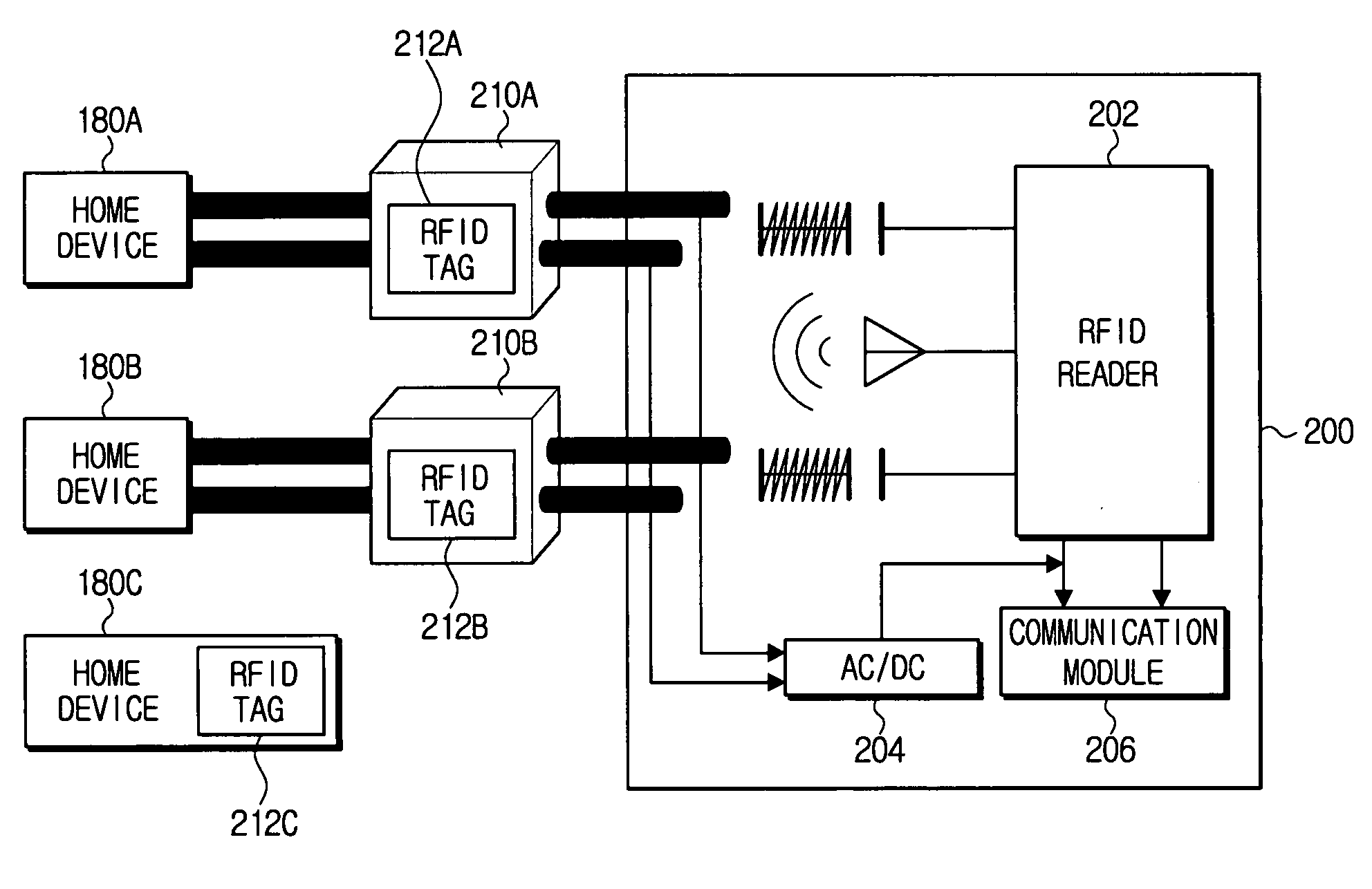
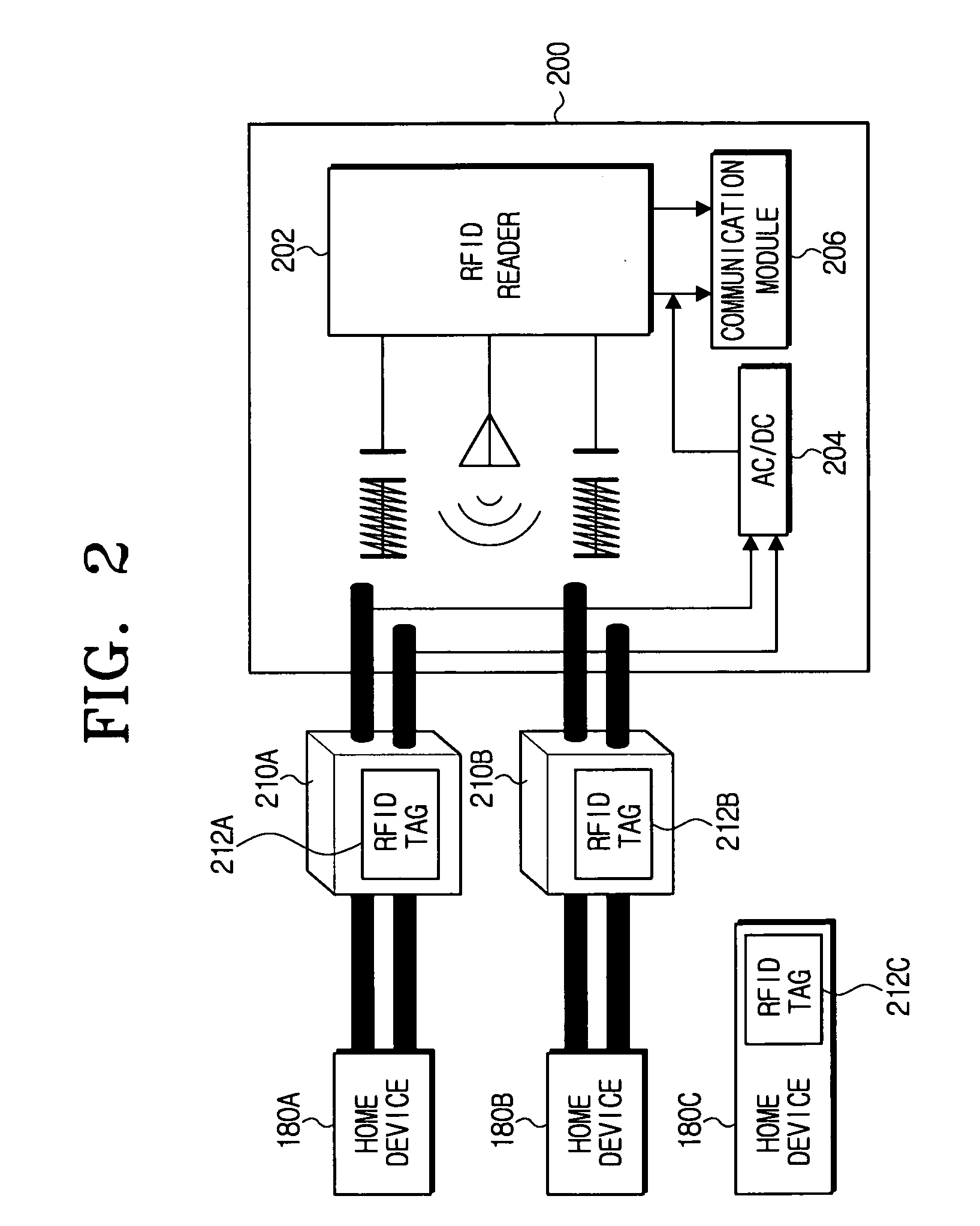
[0028]FIG. 2 is a diagram illustrating home devices (e.g., 180a, 180b, 180c) each of which have an RFID tag (e.g., 212a, 212b, 212c) thereon, and a plug receptacle 200 having an RFID reader 202, according to an exemplary embodiment of the invention. In FIG. 2, home device 180a has a plug 210a (on which RFID tag 212a is provided) which is connected to the plug receptacle 200 to provide power to the home device 180a. Alternatively, a home device 180c may be provided that does not have a plug, but which has an RFID tag 212c thereon. Other configurations may be provided according to a user setup mode. The RFID tags 212a, 212b, 212c each include information about the respective home devices 180a, 180b, 180c (e.g., a ...


PUM


Abstract

A system where a home server can recognize a location of a home device in a home network. The home device includes a Radio Frequency Identification (RFID) tag which stores information about the home device, and each plug receptacle constituting the home network has an RFID reader. Accordingly, the RFID reader checks the location of the RFID tag in real time and transfers the information about the RFID tag and a receptacle identifier to a home server, so that the home server recognizes the location of the home device in real time using the information transferred. Therefore, using the transferred information, the home server can recognize in real-time the location of the home device, and also transfer necessary information to the home device.

Description

CROSS-REFERENCE TO RELATED APPLICATIONS [0001] This application is based upon and claims the benefit of priority under 35 U.S.C. §119 from Korean Patent Application No. 2005-13572 filed on Feb. 18, 2005 in the Korean Intellectual Property Office, the entire content of which is incorporated herein by reference. BACKGROUND OF THE INVENTION [0002] 1. Field of the Invention [0003] Devices, systems, and methods consistent with the invention relate to a home network, and more particularly, to efficiently controlling home devices by recognizing locations of home devices having a communicating function and home devices without a communicating function, as elements of a home network. [0004] 2. Description of the Related Art [0005] A home network is a future home electronic appliance connection system which connects electronic appliances (e.g., a TV, a refrigerator, an air conditioner, etc.) at respective places in a house (e.g., a bedroom, a kitchen, a living room, an entrance, etc.) to the ...

Claims


Application Information

Patent Timeline
IPC IPC(8): G06F15/16
CPCH04L12/2809H04L2012/285H04L67/16H04L67/04H04L67/18H04L67/51H04L67/52A61H39/06A61K36/282A61H2201/0278A61H2201/025A61N2005/066
Inventor HWANG, YOO-SEUNGSHIN, DONG-YUNLIM, HUN
Owner SAMSUNG ELECTRONICS CO LTD
Learn More