
Method and apparatus for EUV plasma source target delivery

a plasma source and target technology, applied in the field of euv light source generators, can solve the problems of unknown existence and unsuitable materials

Inactive Publication Date: 2006-08-31
ASML NETHERLANDS BV
View PDF98 Cites 107 Cited by
  • Summary
  • Abstract
  • Description
  • Claims
  • Application Information

AI Technical Summary

Problems solved by technology

A number of problems are known to exist in the art regarding the delivery timing and positioning of the target at the plasma initiation site which are addressed in the present application.
Magnetostriction (and electrostriction) has been used for ultrasonic transducers in competition with piezoelectric crystals, but so far as applicants are aware, such materials have not been employed to address problems which may be associated with the utilization of piezoelectric materials in the environment of plasma generated EUV light source generators or specifically for target droplet generation in liquid jets target droplet generators.

Method used


Image

  • Method and apparatus for EUV plasma source target delivery
  • Method and apparatus for EUV plasma source target delivery
  • Method and apparatus for EUV plasma source target delivery

Examples


Embodiment Construction

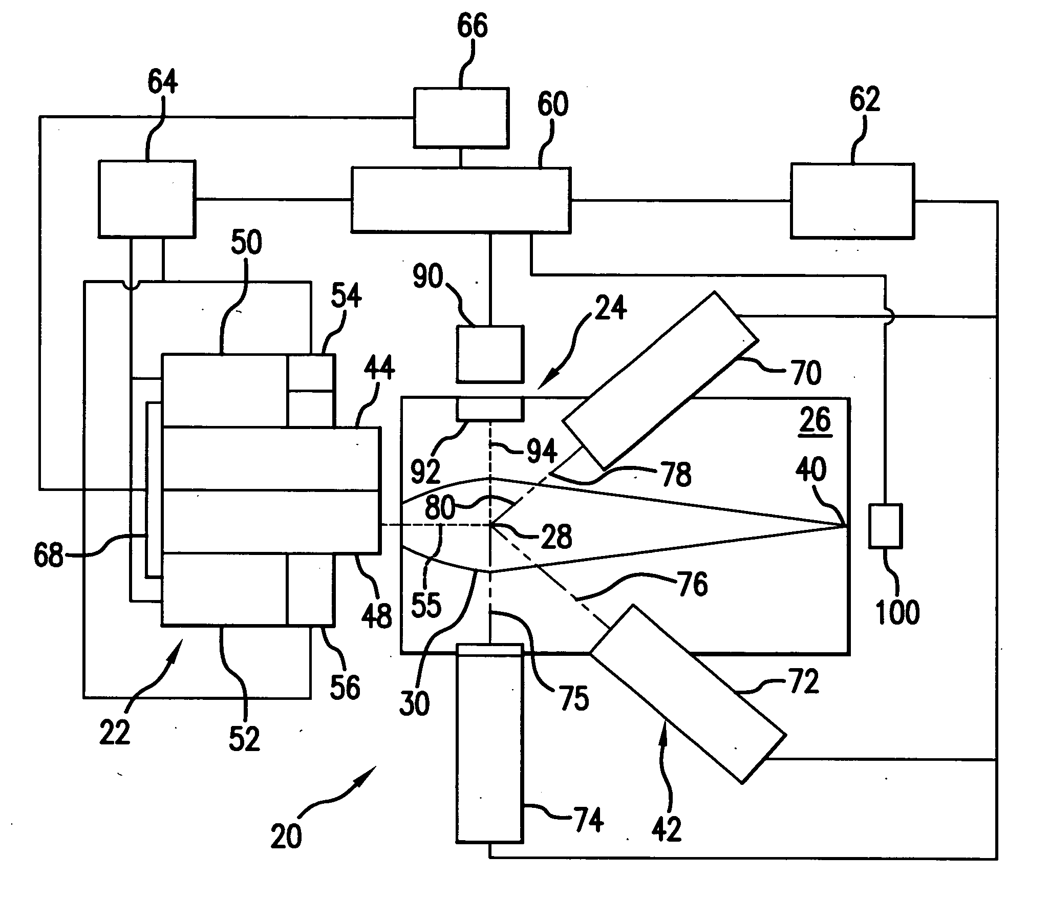
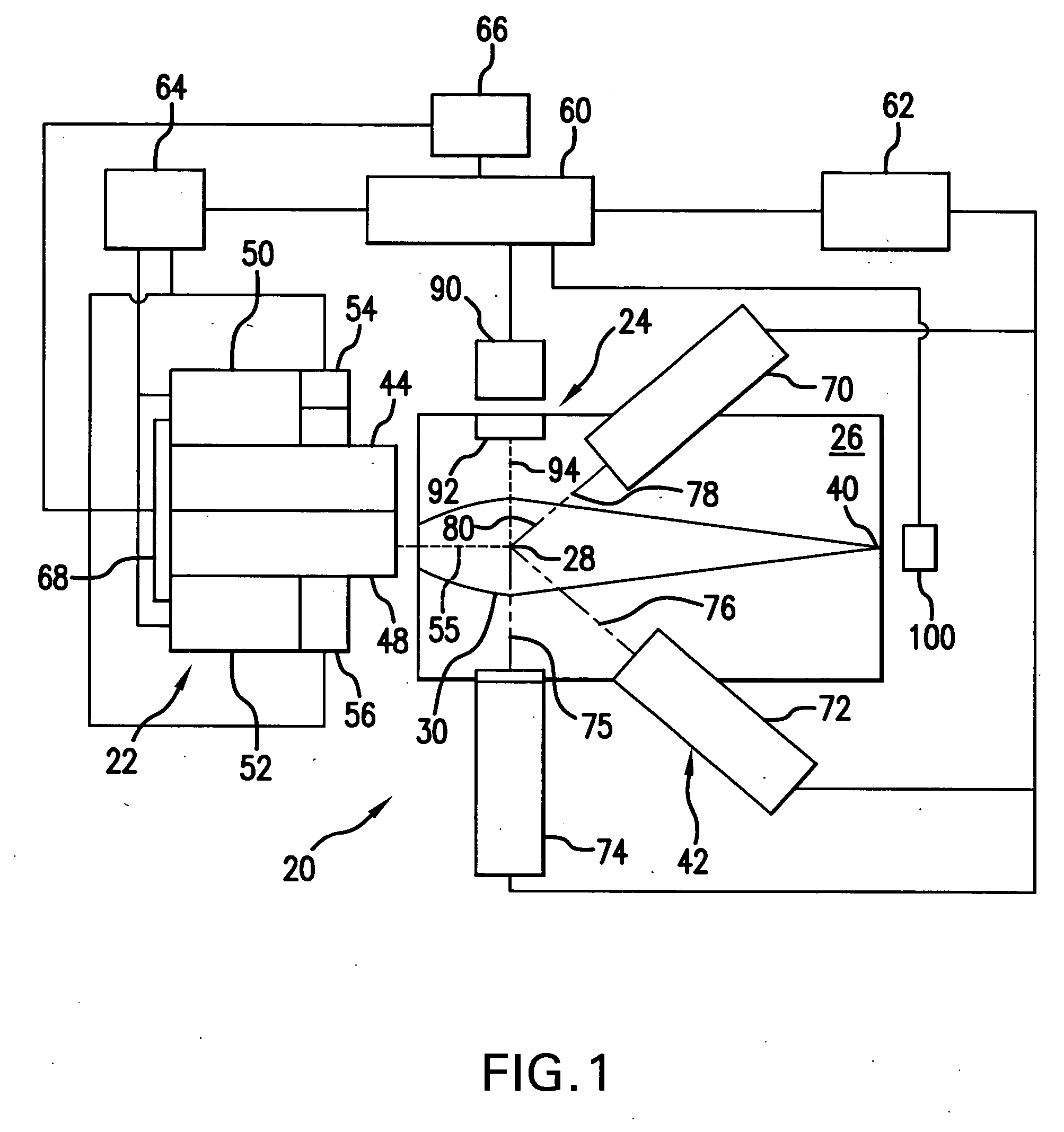
[0020] Turning now to FIG. 1 there is shown a schematic view of an overall broad conception for an EUV light source, e.g., a laser produced plasma EUV light source 20 according to an aspect of the present invention. The light source 20 may contain a pulsed laser system 22, e.g., one or more gas discharge excimer or molecular fluorine lasers operating at high power and high pulse repetition rate and may be one or more MOPA configured laser systems, e.g., as shown in U.S. Pat. Nos. 6,625,191, 6,549,551, and 6,567,450. The light source 20 may also include a target delivery system 24, e.g., delivering targets in the form of liquid droplets, solid particles or solid particles contained within liquid droplets. The targets may be delivered by the target delivery system 24, e.g., into the interior of a chamber 26 to an irradiation site 28, otherwise known as an plasma formation site or the sight of the fire ball, i.e., where irradiation by the laser causes the plasma to form from the target...


PUM

PropertyMeasurementUnit
diameteraaaaaaaaaa
diameteraaaaaaaaaa
diameteraaaaaaaaaa

Abstract

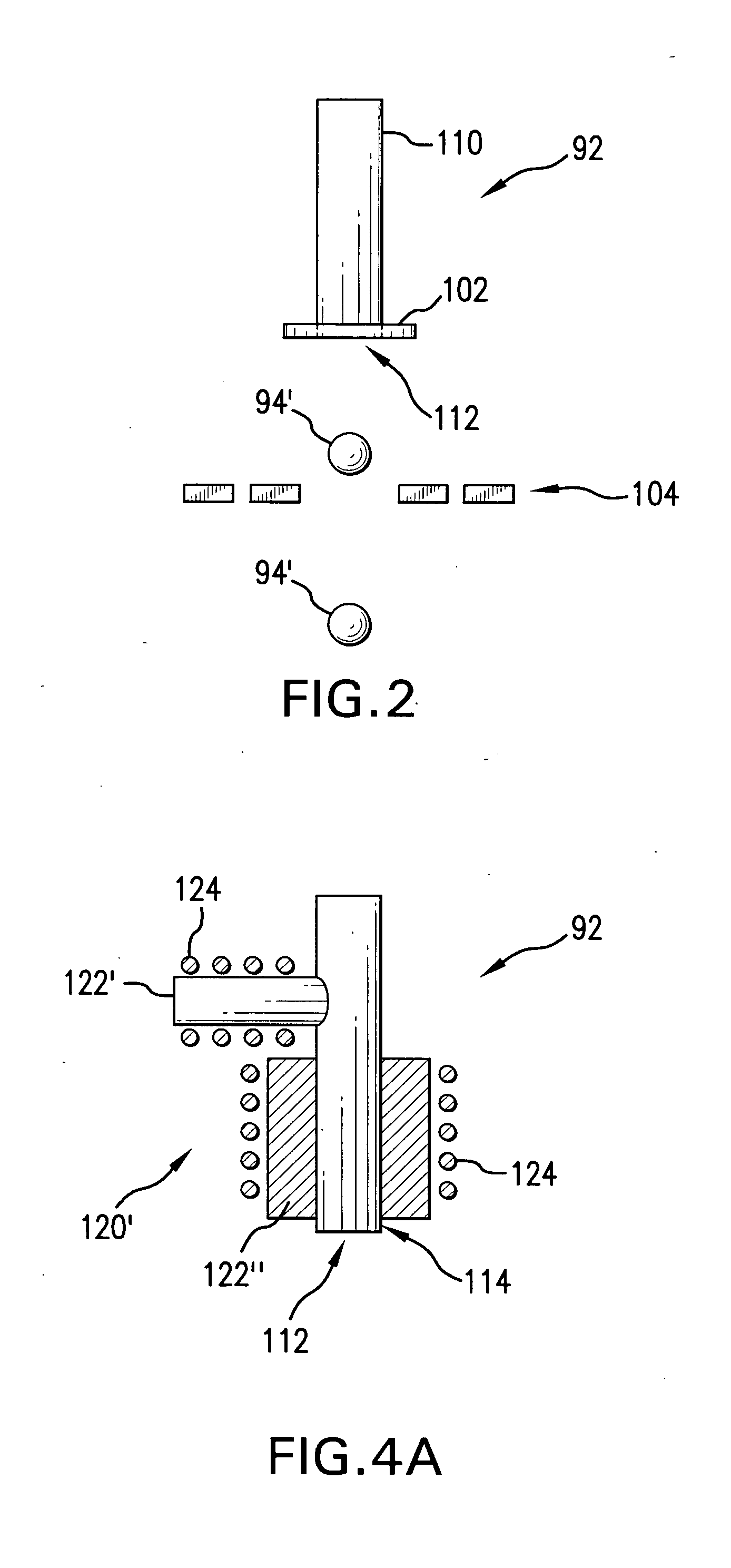
An EUV plasma formation target delivery system and method is disclosed which may comprise: a target droplet formation mechanism comprising a magneto-restrictive or electro-restrictive material, a liquid plasma source material passageway terminating in an output orifice; a charging mechanism applying charge to a droplet forming jet stream or to individual droplets exiting the passageway along a selected path; a droplet deflector intermediate the output orifice and a plasma initiation site periodically deflecting droplets from the selected path, a liquid target material delivery mechanism comprising a liquid target material delivery passage having an input opening and an output orifice; an electromotive disturbing force generating mechanism generating a disturbing force within the liquid target material, a liquid target delivery droplet formation mechanism having an output orifice; and / or a wetting barrier around the periphery of the output orifice.

Description

RELATED APPLICATIONS [0001] The present application is related to co-pending U.S. application Ser. No. ______, entitled EUV Light Source Optical Elements, filed on Dec. 22, 2004, Attorney Docket No. 2004-0023-01, and Ser. No. 10 / 979,945, entitled EUV Collector Debris Management, filed on Nov. 1, 2004, Attorney Docket No. 2004-0088-01, Ser. No. 10 / 979,919, filed on Nov. 1, 2004, entitled LPP EUV Light Source, Attorney Docket No. 2004-0064-01, Ser. No. 10 / 900,839, entitled EUV Light Source, Attorney Docket No. 2004-0044-01, Ser. No. 10 / 798,740, entitled Collector For EUV Light Source, Attorney Docket No. 2003-0083-01, the disclosures of which are hereby incorporated by reference, and to co-pending application Ser. No. ______, entitled Method and Apparatus for EUV Plasma Source Target Delivery Target Material Handling, filed on the same day as the present application, Attorney Docket No. 2004-0097-01, the disclosure of which is also hereby incorporated by reference.FIELD OF THE INVENTI...

Claims


Application Information

Patent Timeline
Patent Type & Authority Applications(United States)
IPC IPC(8): H05G2/00
CPCH05G2/003H05G2/005H05G2/006H05G2/00
Inventor ALGOTS, J. MARTINFOMENKOV, IGOR V.ERSHOV, ALEXANDER I.PARTLO, WILLIAM N.SANDSTROM, RICHARD L.HEMBERG, OSCARBYKANOV, ALEXANDER N.COBB, DENNIS W.
Owner ASML NETHERLANDS BV
Learn More