System and method for automatic tuning of a magnetic field generator

a generator and automatic tuning technology, applied in discontinuous tuning with variable tuning elements, line-transmission details, therapy, etc., can solve the problems of deteriorating communication integrity between the microdevice and its control unit, corresponding negative effect of any magnetic field generated by the inductor, etc., to maximize the power delivered to the tuned circuit, maximize the power delivered, and maximize the effect of power delivered

Active Publication Date: 2006-08-31
ALFRED E MANN FOUND FOR SCI RES
View PDF17 Cites 33 Cited by
  • Summary
  • Abstract
  • Description
  • Claims
  • Application Information

AI Technical Summary

Benefits of technology

[0005] The present invention addresses the need to provide an automatic tuning system that efficiently and adaptively maximizes the power delivered to a tuned circuit that includes a magnetic field generating inductor. In accordance with an embodiment of the invention, a microcontroller based automatic tuning system is provided that includes a power source, a tuned circuit comprising an inductor and an adjustable capacitor, a power amplifier having an input coupled to a reference frequency generator and an output configured to drive the tuned circuit. The inductance value of the inductor and the capacitance value of the variable capacitor establishes the resonant frequency of the tuned circuit which is automatically tuned such that the resonant frequency is adjusted to equal the reference frequency. Normally, when the resonant frequency of the tuned circuit equals the reference frequency, maximum power will be delivered to the tuned circuit. A sense circuit is arranged to provide a signal to the microcontroller corresponding to the power delivered by the power amplifier to the tuned circuit. The microcontroller causes the variable capacitor to be adjusted so as to maximize the power delivered to the tuned circuit. In an alternate embodiment, the phase of the reference frequency and the phase of the current flowing through the inductor are compared and maintained within a predetermined range in order to maximize the power delivered to the tuned circuit.
[0011] The frequency at which the capacitor adjustment process is undertaken as well as the time between capacitor switching during the maximum power determining process, may be set depending upon the expected nature of inductance value changes in normal operation. Nominally, the time to complete the full capacitor switching protocol is about 750 milliseconds and the time to the next determination of the tuned circuit operating point is one millisecond after establishing the capacitor switch setting that maximizes power delivery to the tuned circuit.

Problems solved by technology

This can occur if the inductor is bent or distorted when applied to fit the contour of a desired location of a body.
Changes in inductance value of the inductor may have a severe impact on the resonant frequency of the tuned circuit and therefore have a correspondingly negative effect on any magnetic field generated by the inductor.
The fallout from such deterioration of magnetic field strength would be the deterioration of communication integrity between the microdevice and its control unit.
Failing to achieve the maximum power delivery condition, the microcontroller issues an error message indicating a major malfunction, such as a disconnect of the inductor from the tuned circuit.

Method used


Image

  • System and method for automatic tuning of a magnetic field generator
  • System and method for automatic tuning of a magnetic field generator
  • System and method for automatic tuning of a magnetic field generator

Examples


Embodiment Construction

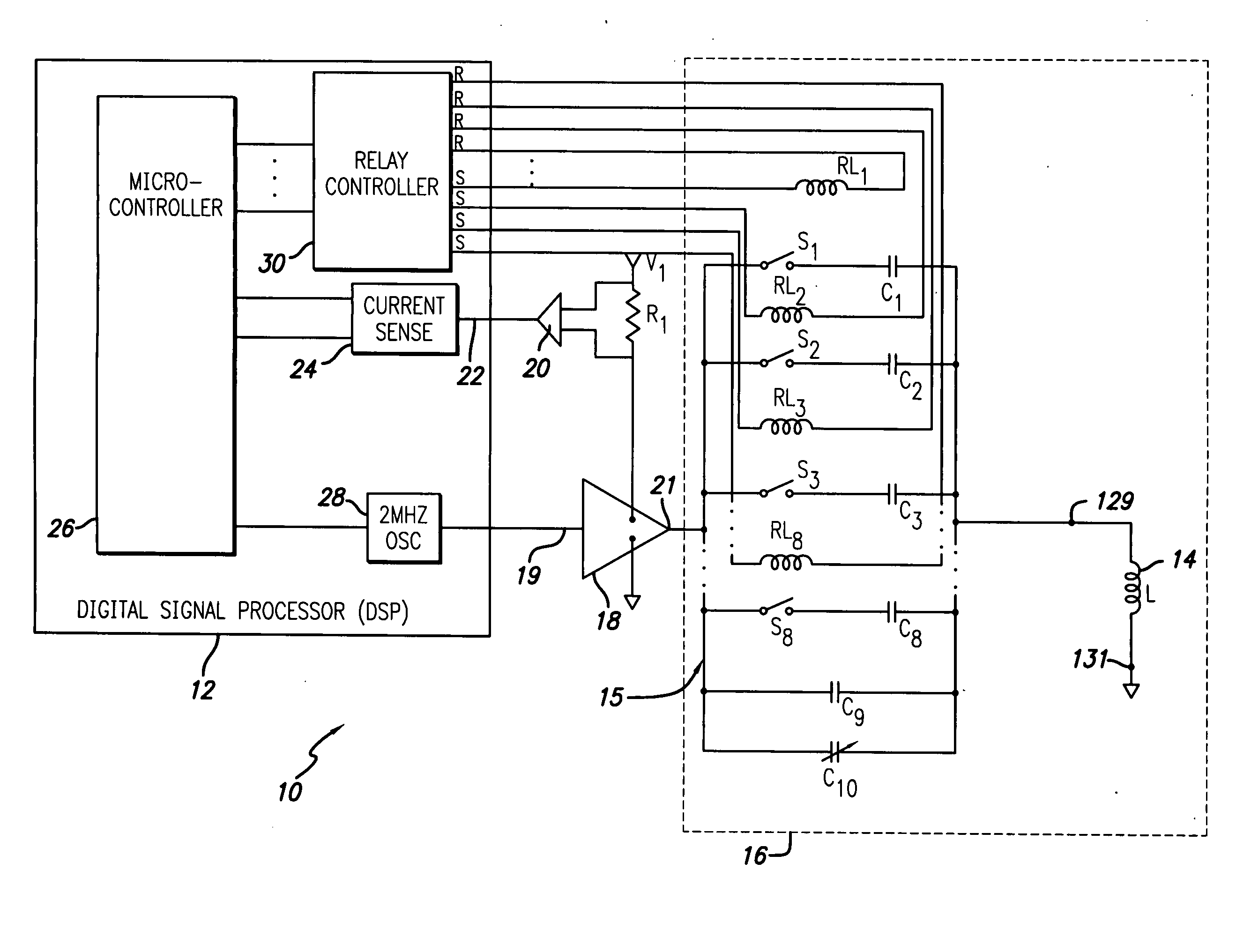
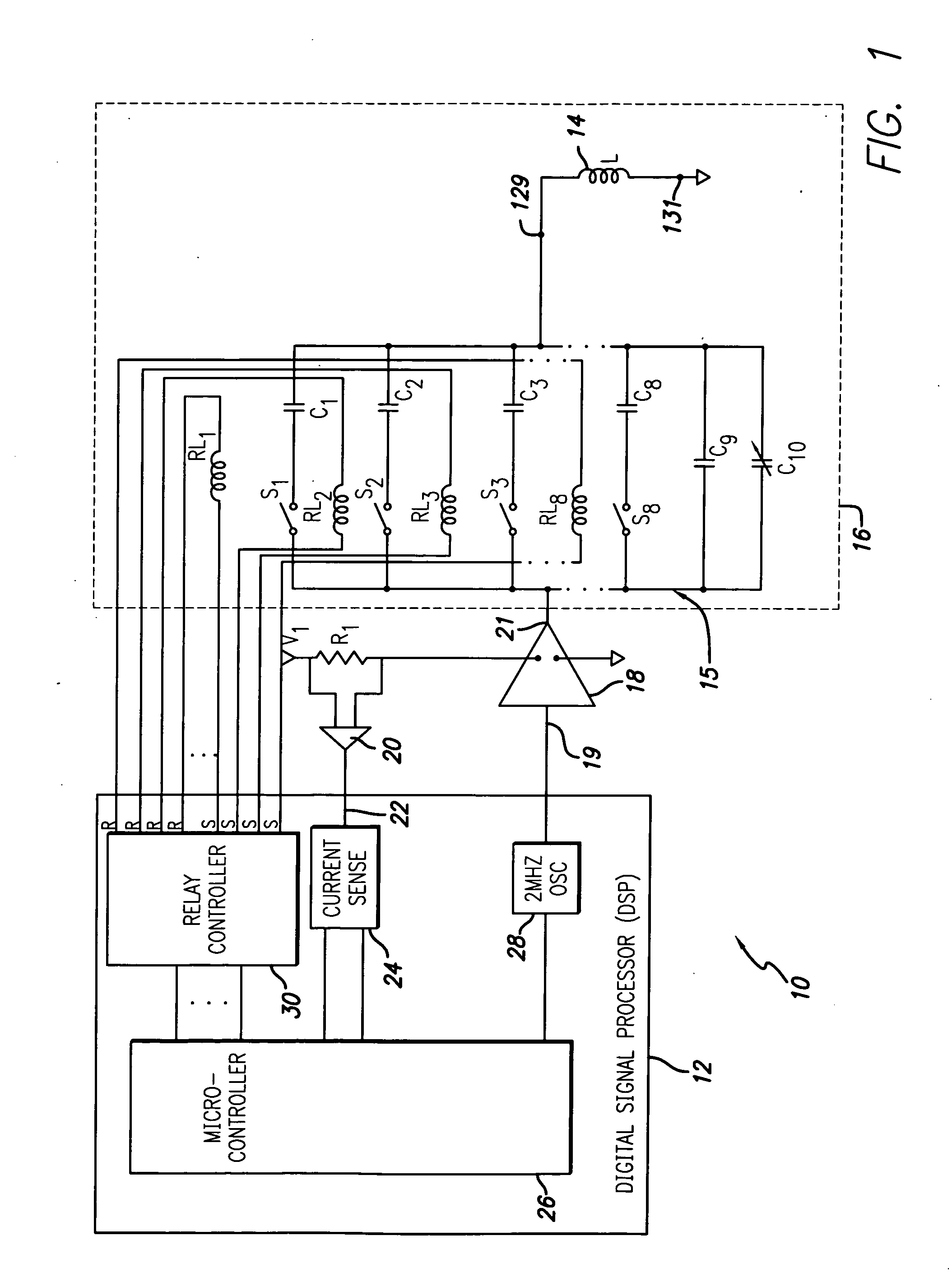
[0040] Referring now to FIG. 1 there is shown in schematic format, a block diagram of an embodiment of the present invention. The automatic tuning system 10 includes a digital signal processor (DSP) 12, a magnetic field generating inductor 14, a bank of switchable capacitors 15, a power amplifier 18 and a sense amplifier 20 that includes resistor R1. Broadly, the capacitor bank 15 and inductor 14 form a tuned circuit 16 having a resonant frequency that is determined by the value of inductance of inductor 14 and the capacitance value of the capacitor bank 15. The tuned circuit is driven by power amplifier 18 which obtains operating power from source V1 through resistor R1. The input 19 of power amplifier 18 is coupled to a reference oscillator 28 located on DSP 12. Although any of a number of reference frequencies may be considered, for the present invention, a reference oscillator frequency of 2 MHZ is preferable. By virtue of the connection of power amplifier 18 to the reference os...


PUM


Abstract

An automatic tuning system for a magnetic field generating tuned circuit includes a processor configured to maintain the resonant frequency of a tuned circuit equal to a reference frequency. The tuned circuit is driven by a power amplifier whose output provides an amplified signal at the reference frequency. The tuned circuit includes a magnetic field generating inductor and a bank of individually switchable capacitors controlled by the processor capable of adding and removing the respective capacitances to and from the tuned circuit. The inductor includes a Faraday shield to shield the tuned circuit from the influence of electric fields. In an embodiment of the invention, the variable capacitor is in the form of a diode variable capacitor (varicap) in parallel circuit relationship with the tuned circuit capacitor and the inductor. In an alternate embodiment the inductor and a fixed capacitor are in series circuit relationship with the varicap in parallel circuit relationship with the fixed capacitor and the tuning sequence relies on a phase locked loop using the phase of a reference frequency signal and the phase of the inductor voltage as control parameters.

Description

CROSS REFERENCE TO RELATED APPLICATION [0001] This application is a continuation-in-part of U.S. non-provisional application No. 10 / 429,427 filed May 5, 2003. This application also claims the benefit of U.S. provisional application No. 60 / 661,760 filed Mar. 14, 2005.FIELD OF THE INVENTION [0002] The present invention relates to a system and method for tuning a magnetic field generator, more particularly, to a system and method that automatically provides efficient power transfer from a power source to a tuned circuit having a magnetic field generating inductor. BACKGROUND OF THE INVENTION [0003] Implantable medical devices for remedial treatment of and compensation for cardiac, neural and muscular disorders, are known in the art. These devices range from cardiac pacemakers as described in U. S. Pat. No. 4,712,555 to Thornander et al., to microstimulators as described in U. S. Pat. No. 6,208,894 to Schulman et al. The quest for minimization of such devices, especially in the area of ...

Claims


Application Information

Patent Timeline
Patent Type & Authority Applications(United States)
IPC IPC(8): H04B3/04
CPCA61N1/3787H03J5/02H03J2200/10H03L5/02A61N1/37229
Inventor SCHULMAN, JOSEPH H.VOGEL, MARTIN J.VOGEL, ADAMHANCOCK, DONALD J.LEWIS, DALE
Owner ALFRED E MANN FOUND FOR SCI RES
Why Eureka
Try Eureka