Optical communication system

Active Publication Date: 2006-08-31
FUJIFILM HLDG CORP +1
View PDF4 Cites 14 Cited by
  • Summary
  • Abstract
  • Description
  • Claims
  • Application Information

AI Technical Summary

Benefits of technology

[0022] More specifically, in order to achieve a transmission loss level of less than or equal to 200 dB/km, which is the target loss level for practical use, it is necessary to limit the beam diameter less than or equal to approximately 250 μm, and the numerical aperture less than or equal to approximately 0.25 for the light beam incident on the GI-POF input face. More preferably, it is necessary to limit the beam diameter less than or equal to approximately 200 μm, and the numerical aperture less than or equal to approximately 0.2 for the light beam incident on the GI-POF input face. Based on this knowledge, the optical communication system of the present inven

Problems solved by technology

Consequently, installation work for optical fibers under common environments, including construction sites or the like, is no easy task.
This has been an obstacle that lies in the way toward wider use of optical c

Method used


Image

  • Optical communication system
  • Optical communication system
  • Optical communication system

Examples


case 1

[0033] Use of a Semiconductor Laser Having a Single Luminous section (Edge Emitting Type or VCSEL)

[0034] For the light source that may be deemed as an ideal point light source, such as a semiconductor laser that emits light from a single spot, the design target values described above may be achieved with relative ease. Firstly, the diameter of the luminous section of the semiconductor laser of edge emitting type or VCSEL is less than or equal to 20 μm, and the divergence angle of the light beam emitted from the luminous section expressed in terms of numerical aperture is less than or equal to 0.6 at most. Hereinafter, the divergence angle of the light beam emitted from the light source expressed in terms of numerical aperture is also referred to as “emission NA”, and the divergence angle expressed in terms of numerical aperture of the light incident on the input face of the optical fiber is also referred to as “incident NA”. Further, the average beam diameter of the light at the in...

case 2

[0038] Use of an Array VCSEL Constituted by a Plurality of Luminous Sections

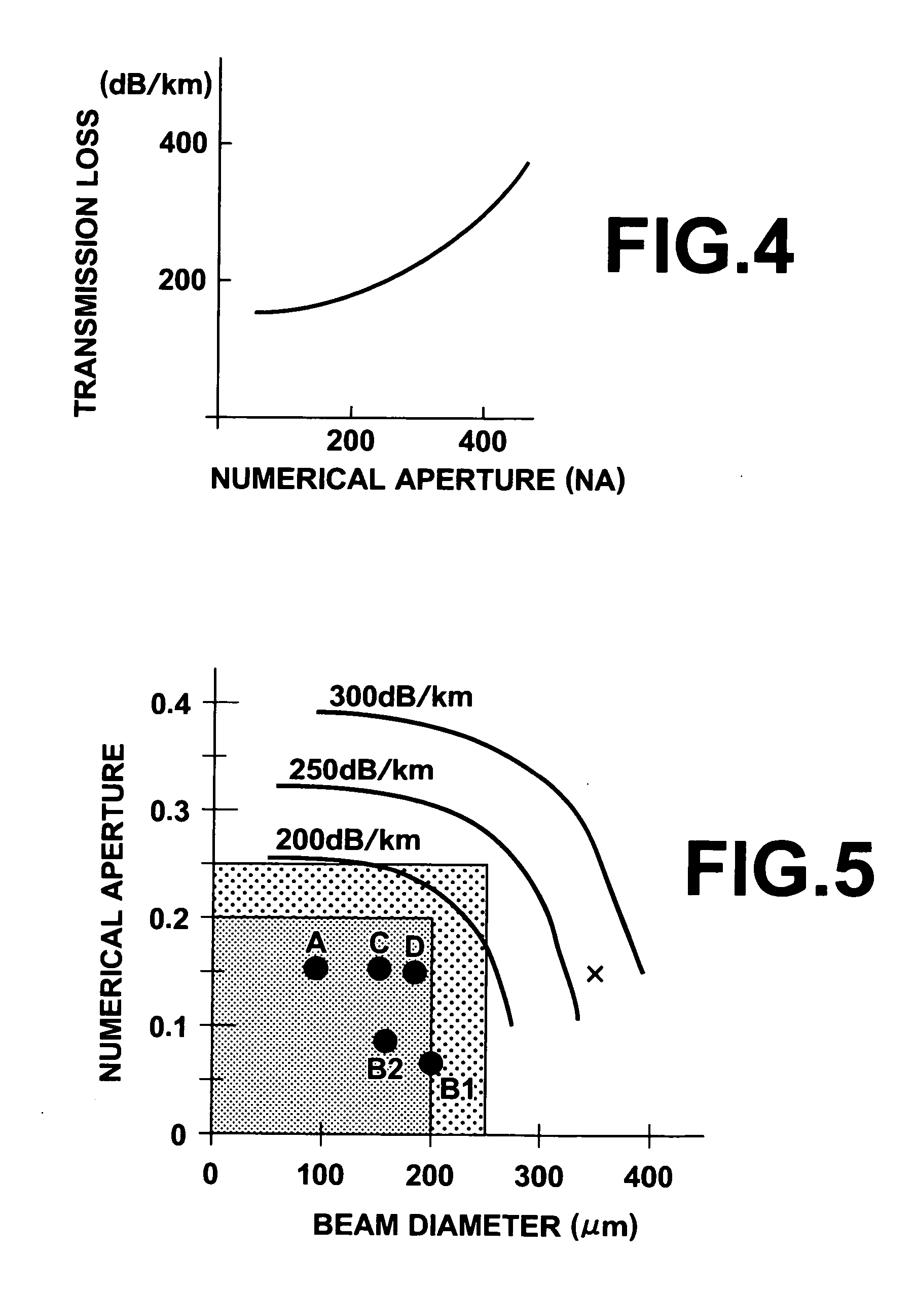
[0039] For a VCSEL having a plurality of luminous sections, it is necessary to take into account the distance between the luminous sections. Supposing the case in which a four spot array VCSEL having luminous sections 20 on the surface of a square shown in FIG. 6 is used here. If the spot distance is 50 μm, the distance along the diagonal line is 70 μm. If the diameter of each of the luminous section is 10 μm, the VCSEL should be deemed to be an equivalent to the light source having a maximum outer dimension of 80 μm. If the emission NA of the array VCSEL 21 is assumed to be 0.3, an incident beam diameter of 160 μm, and an incident NA of 0.15 may be achieved by using an optical system of 2× magnifying power. This result falls well within the optimum region (point C in FIG. 5).

case 3

[0040] Use of RC-LED

[0041] In this case, aRC-LED having a luminous section with a diameter in the range from 50 to 100 μm is generally selected in view of reliability. That is, a smaller diameter of the luminous section results in an unfavorably excessive current density. Accordingly, the diameter of the luminous section may be considered in the same way as in the case 2 where a semiconductor laser having a plurality of luminous sections is used as the light source. If the diameter of the luminous section of the RC-LED is assumed to be 100 μm, and emission NA is assumed to be 0.3, an incident beam diameter of 180 μm and an incident NA of 0.17 (approximately ½ of the emission NA) may be achieved by using an optical system of 1.8× magnifying power. This result falls well within the optimum region (point D in FIG. 5).

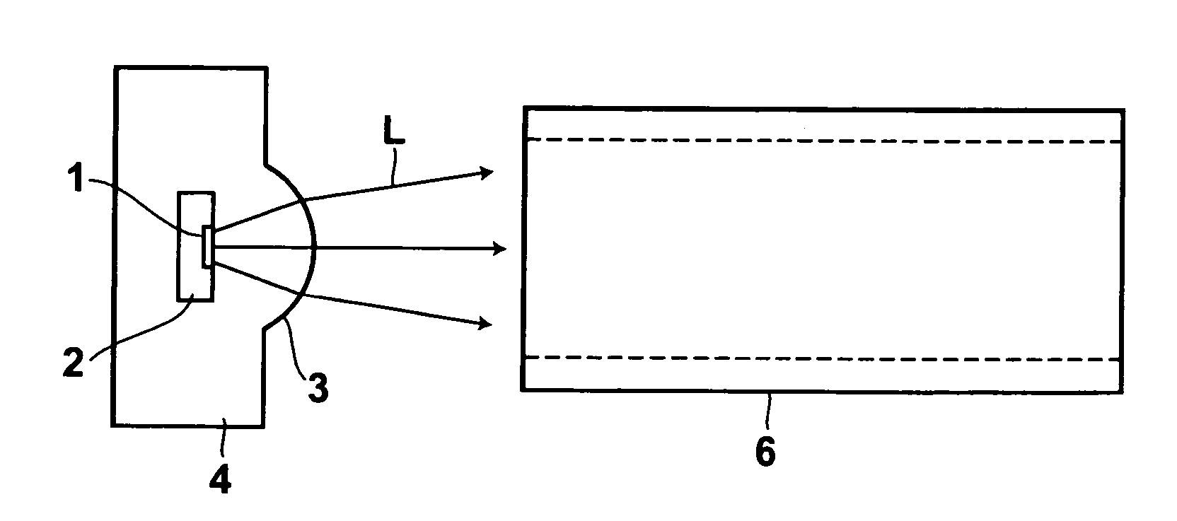
[0042] Hereinafter, a more specific embodiment will be described. FIG. 1 is a schematic block diagram of the optical communication system according to the present embodi...


PUM


Abstract

In an optical communication system in which communication is conducted by transmitting light through a plastic optical fiber with a core diameter in the range from 300 to 600 μm, the average beam diameter and beam divergence angle expressed in terms of numerical aperture (NA) of the light at the input face of the optical fiber are set less than or equal to 250 μm, more preferably less than or equal to 200 μm, and less than or equal to 0.25, more preferably less than or equal to 0.2 respectively.

Description

BACKGROUND OF THE INVENTION [0001] 1. Field of the Invention [0002] The present invention relates to an optical communication system that uses a plastic optical fiber as the transmission line. [0003] 2. Description of the Related Art [0004] In optical communication systems, single mode or multimode optical fibers made mainly of silica glass have been used as the optical transmission lines. In general, the core diameter of these optical fibers is less than 100 μm, and very precise core alignment with an allowance of few micrometers is required when splicing the fibers. Consequently, installation work for optical fibers under common environments, including construction sites or the like, is no easy task. This has been an obstacle that lies in the way toward wider use of optical communication systems using optical fibers. [0005] In the mean time, plastic optical fibers having larger core diameters for use with optical communication systems have also been developed as described, for exa...

Claims


Application Information

Patent Timeline
IPC IPC(8): G02B6/02G02B6/42H04B10/2581H04B10/25
CPCG02B6/02038G02B6/4206
Inventor MATSUMOTO, KENJITAKAHASHI, HIROKI
Owner FUJIFILM HLDG CORP
Why Eureka
Try Eureka