Minimally invasive transvalvular ventricular assist device

a technology of ventricular assist and minimal invasiveness, which is applied in the direction of heart stimulators, prostheses, therapy, etc., can solve the problems of poor reliability, no device developed to date has been recognized by surgeons, cardiologists, and the public, and none has yet reduced the incidence of serious adverse events to a practically negligible rate. , to achieve the effect of high miniaturization and effectiv

Active Publication Date: 2006-08-31
JARVIK ROBERT
View PDF17 Cites 145 Cited by
  • Summary
  • Abstract
  • Description
  • Claims
  • Application Information

AI Technical Summary

Benefits of technology

[0013] 1. It is an object of the present invention to provide a highly miniaturized and effective heart assist device able to be implanted by minimally invasive surgical techniques.

Problems solved by technology

The pusher plate and other types of positive displacement pumps approved by the FDA are large, heavy, and generally noisy devices which have major limitations, including poor reliability and a high incidence of serious adverse events such as bleeding, infection, thromboembolism, and stroke.
Although rotary blood pumps of many designs represent a very promising improvement over the old generation positive displacement VADs, none has yet reduced the incidence of serious adverse events to a practically negligible rate.
Earlier application of the less invasive rotary blood pumps holds promise to reduce early mortality, but no device developed to date has been recognized by surgeons, cardiologists, and the public as a true “breakthrough device” appropriate to implant in NYHA class III patients, who have serious heart failure but are not yet facing a risk of imminent death.
No heart assist device is better than its worst characteristic.
If everything were perfect except the durability were less than two years the device would have limited usefulness for permanent implantation.
If it were durable for decades but had a very high incidence of serious infection, it would find limited use.
If it had excellent long term freedom from failure and no serious adverse events, but required highly invasive surgery, with high surgical mortality and prolonged post implant hospitalization, it would not be widely accepted.
Experience also teaches that despite the greatest care to prevent damage to external components, such as batteries, cables, and connectors, and despite concerted efforts to educate patients and caregivers in proper daily use, damage, mistakes, and oversights can never be completely avoided.
Regarding complexity, almost all VADS have significant problems associated with the inflow and outflow conduits used to connect the devices to the circulatory system.
But it still requires an outflow graft which must be sutured to the aorta and has been the site of bleeding complications.
Despite elimination of the inlet and outlet cannulae, pump placement within the entire valve orifice, as disclosed in the prior art, has significant disadvantages.
If the pump stops, the patient's natural heart has no valved outlet, and therefore it cannot pump effectively to support the patient even for a short time.
If an axial pump with a large cross sectional flow area is used, there will be massive aortic regurgitation and the natural heart will fail.
If an axial pump with a small cross sectional flow area is used, there may be little regurgitation, but there will be high resistance and the natural heart will not be able to eject sufficient blood.
However, in any pump where a cylindrical cannula is passed through the central portion of the aortic valve and the leaflets must seal against the cannula, the shape of the valve leaflets does not exactly match the cannula.
These factors make the valve leaflets subject to erosion if the cannula is left in place long term.

Method used


Image

  • Minimally invasive transvalvular ventricular assist device
  • Minimally invasive transvalvular ventricular assist device
  • Minimally invasive transvalvular ventricular assist device

Examples


Embodiment Construction

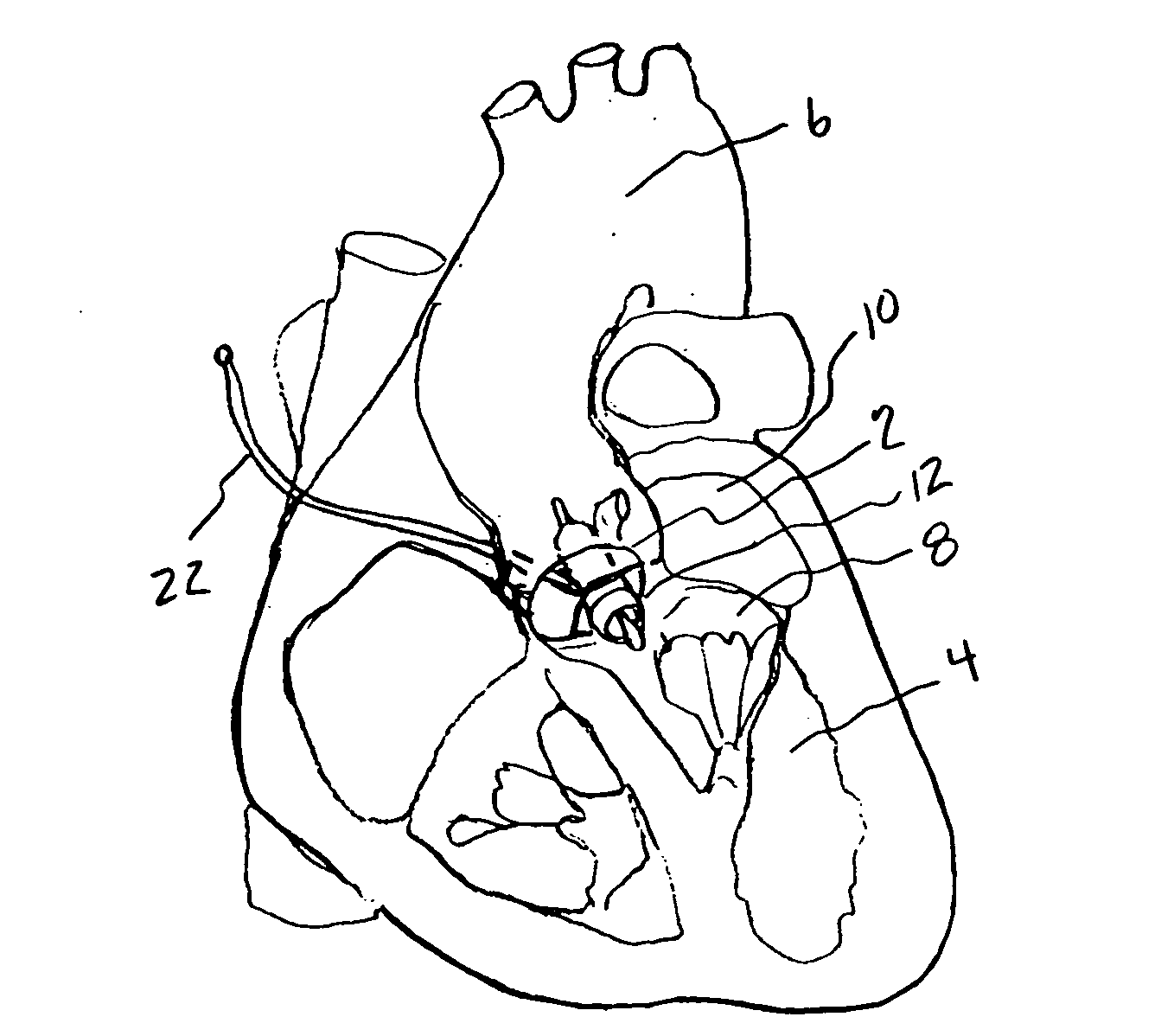
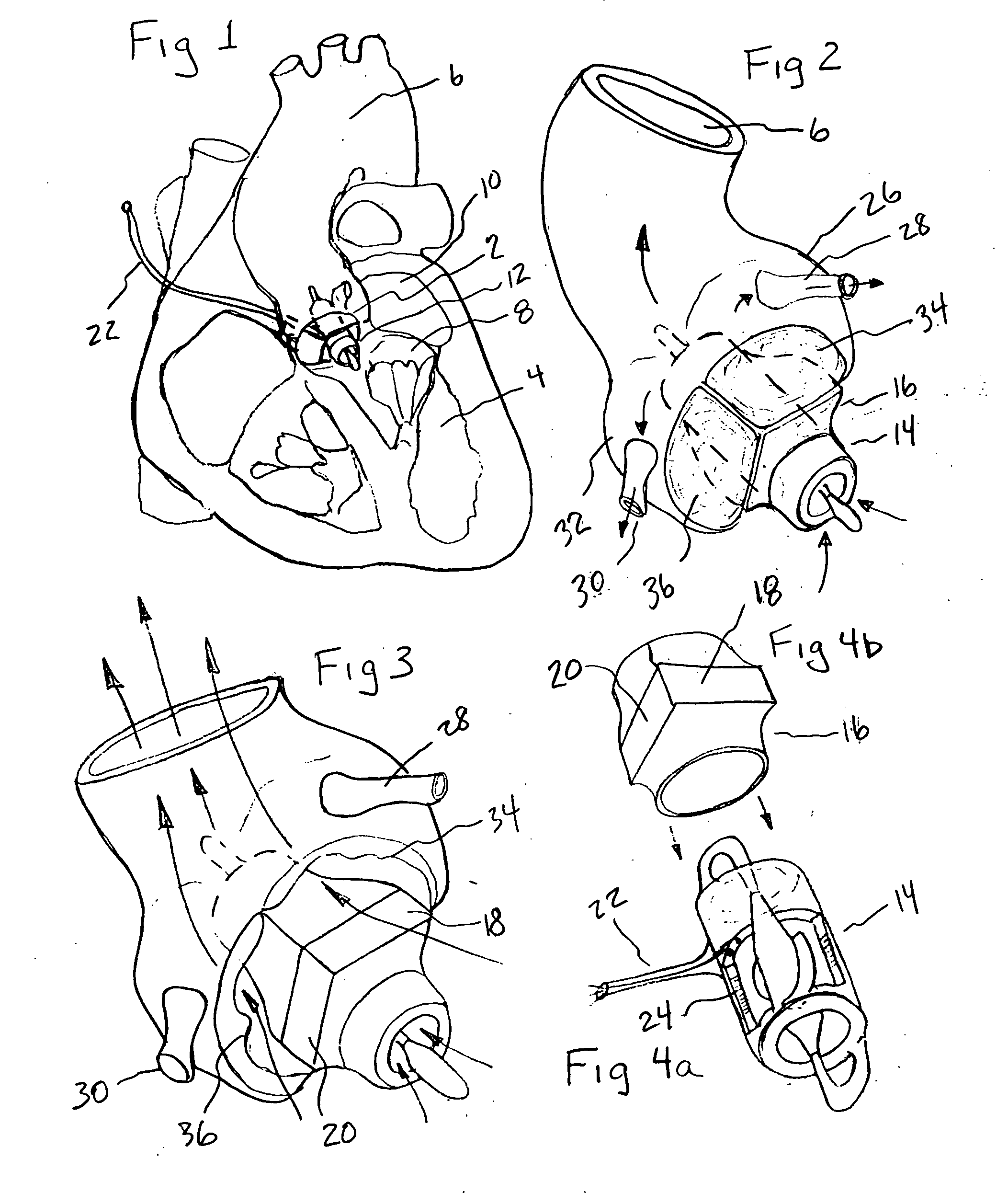
[0032] The present invention provides a miniature blood pump which fits within the cross sectional area of one of the three leaflets of either the aortic or pulmonary valve, with the pump inlet side having unobstructed communication with the ventricular cavity and the pump outlet located in the aorta or pulmonary artery distal to the valve leaflets. Referring to FIG. 1 which is a cut away drawing of the heart with the anterior portion of the left and right ventricles removed, the aortic valve 2, is located between the left ventricle 4, and the aorta 6. The mitral valve 8, is located between the left ventricle 4, and the left atrium 10. A transvalvular VAD 12, is implanted into the non-coronary sinus of the aortic valve, which is located adjacent to the mitral valve 8. In the preferred embodiment it is comprised of a miniature axial flow pump 14, best seen in FIG. 4a, and a shaped anatomic adaptor 16, best seen in FIG. 4b. The anatomic adaptor has two facet like surfaces 18, 20, that...


PUM


Abstract

A tiny electrically powered hydrodynamic blood pump is disclosed which occupies one third of the aortic or pulmonary valve position, and pumps directly from the left ventricle to the aorta or from the right ventricle to the pulmonary artery. The device is configured to exactly match or approximate the space of one leaflet and sinus of valsalva, with part of the device supported in the outflow tract of the ventricular cavity adjacent to the valve. In the configuration used, two leaflets of the natural tri-leaflet valve remain functional and the pump resides where the third leaflet had been. When implanted, the outer surface of the device includes two faces against which the two valve leaflets seal when closed. To obtain the best valve function, the shape of these faces may be custom fabricated to match the individual patient's valve geometry based on high resolution three dimensional CT or MRI images. Another embodiment of the invention discloses a combined two leaflet tissue valve with the miniature blood pump supported in the position usually occupied by the third leaflet. Either stented or un-stented tissue valves may be used. This structure preserves two thirds of the valve annulus area for ejection of blood by the natural ventricle, with excellent washing of the aortic root and interface of the blood pump to the heart. In the aortic position, the blood pump is positioned in the non-coronary cusp. A major advantage of the transvalvular VAD is the elimination of both the inflow and outflow cannulae usually required with heart assist devices.

Description

BACKGROUND OF THE INVENTION [0001] Mechanical circulatory support devices have gained increasingly common use in end stage heart failure patients. Presently, more than a thousand patients per year are treated with implantable ventricular assist devices (VADs), as bridge to transplant, bridge to recovery, or for permanent use. The pusher plate and other types of positive displacement pumps approved by the FDA are large, heavy, and generally noisy devices which have major limitations, including poor reliability and a high incidence of serious adverse events such as bleeding, infection, thromboembolism, and stroke. Over the past five years, rotary blood pumps have been undergoing clinical trials in the United States, or have received CE mark approval for use abroad. The Jarvik 2000 intraventricular axial flow pump VAD, has been used in over 100 patients, and has supported a patient almost five years, longer than any other single VAD of any type. One patient has survived for over 6 year...

Claims


Application Information

Patent Timeline
Patent Type & Authority Applications(United States)
IPC IPC(8): A61M1/10A61M60/139A61M60/17A61M60/237A61M60/88A61M60/896
CPCA61M1/101A61M1/12A61M1/122A61M1/125B33Y80/00A61M60/414A61M60/148A61M60/88A61M60/896A61M60/139A61M60/237A61M60/17
Inventor JARVIK, ROBERT
Owner JARVIK ROBERT
Why Eureka
Try Eureka