Frame assembly for a motorcycle

a frame assembly and motorcycle technology, applied in the direction of folding cycles, cycles, transportation and packaging, etc., can solve the problems of excessive stress and lowering manufacturing productivity, and achieve the effects of short time, enhanced manufacturing productivity, and reduced welding length

Active Publication Date: 2006-09-07
HONDA MOTOR CO LTD
View PDF6 Cites 19 Cited by
  • Summary
  • Abstract
  • Description
  • Claims
  • Application Information

AI Technical Summary

Benefits of technology

[0025] According to the third aspect of the invention, the frame assembly is cast from an aluminum alloy and is composed of three component parts arranged sequentially in the front-rear direction, so that when the three component parts of the frame assembly are dividedly distributed so that the two front-side component parts are located on the main frame side whereas the one rear-side component part is located on the rear frame portion side, the two front-side component parts and the one rear-side component part can be formed in structures suitable for the respective portions, the left-right assembly errors can be reduced, and the frame assembly can be formed with high accuracy. In addition, when connecting the three component parts by welding, it is possible to reduce the lengths of welds, to achieve the welding in a short time, and to enhance manufacturing productivity.
[0026] Further, since the two rear-side component parts of the three component parts of the frame assembly are coupled on the rear side of the vehicle frame relative to the portion where the sectional area of the main frame is the smallest, it is possible to ensure that a stress concentration is not liable to occur on the coupling portion between the two rear-side component parts, to further reduce the sectional area of the coupling portion, and to achieve a reduction in weight of the frame assembly.
[0027] According to the fourth aspect of the invention, the single main frame is bisected in the front-rear direction of the vehicle body, so that it is possible to reduce the left-right assembly errors of the main frame, and to form the main frame with high accuracy. In addition, the respective members of the split main frame are easier to produce, and manufacturing productivity is enhanced.
[0028] According to the fifth aspect of the invention, the split and welded portions of the frame assembly are provided respectively at a portion on the front side and at a portion on the rear side relative to the position where the sectional area of the main frame is the smallest, so that the split and welded portions are located so as to avoid the position where the sectional area of the main frame is the smallest. For example, the split and welded portions are located so as to avoid the portion where the frame rigidity is the lowest, whereby generation of an excessively high stress is obviated. In addition, since large-type hollow casting can be obviated, it is easy to achieve the hollow casting of the main frame.
[0029] According to a sixth aspect of the invention, the engine hanger portion is a structurally separate member from the main body of the frame, so that when the hanger portion is formed by gravity casting, the flow of the molten metal in the engine hanger portion is enhanced, and casting quality is enhanced.
[0030] According to the seventh aspect of the invention, the single main frame is composed of a hollow member varied in sectional shape from one portion of the main frame to another portion, so that the rigidity of the main frame can be varied from one portion to another portion, and the main frame can be reduced in weight.

Problems solved by technology

As a result, the welding operation is lengthy so that manufacturing productivity is lowered.
Further, while bending stress is increased at the smallest sectional area portion of the main frame, which is located at substantially the center in the longitudinal direction of the main frame, the arrangement of the coupling portion between the front and rear component parts of the frame assembly on the rear side of the smallest sectional area portion ensures that stress is not concentrated on the coupling portion, and that an excessively high stress is not generated.

Method used


Image

  • Frame assembly for a motorcycle
  • Frame assembly for a motorcycle
  • Frame assembly for a motorcycle

Examples


first embodiment

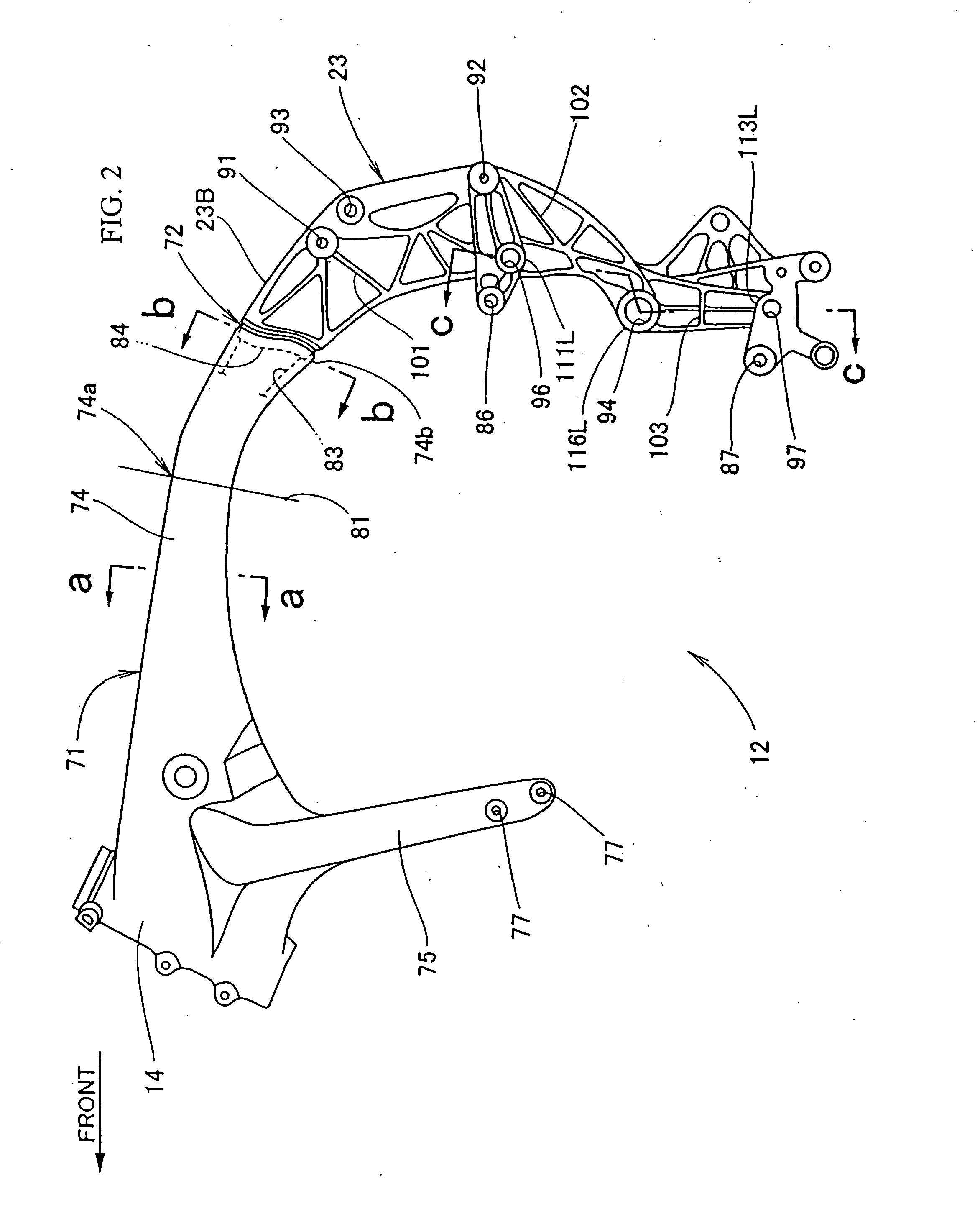
[0050]FIG. 2 is an isolated side plan view (the arrow labeled “FRONT” in the figure indicates the direction corresponding to the front side of the vehicle) of a main frame according to the first embodiment of the present invention. The main frame 12 of FIG. 2 is cast from an aluminum alloy, and includes two primary component parts arranged serially in the front-to-rear direction of the vehicle. Specifically, the main frame 12 includes a front component part and a rear component part, namely, a front frame portion 71 on the front side, and the rear frame portion 23 connected to the rear end of the front frame portion 71 by welding. In the Figures, symbol 72 denotes a welded coupling portion between the front frame portion 71 and the rear frame portion 23.

[0051] The front frame portion 71 is a member that is formed so as to be hollow by placing a core within the mold for the front frame portion 71 at the time of casting. The front frame portion 71 integrally includes the head pipe 14...

second embodiment

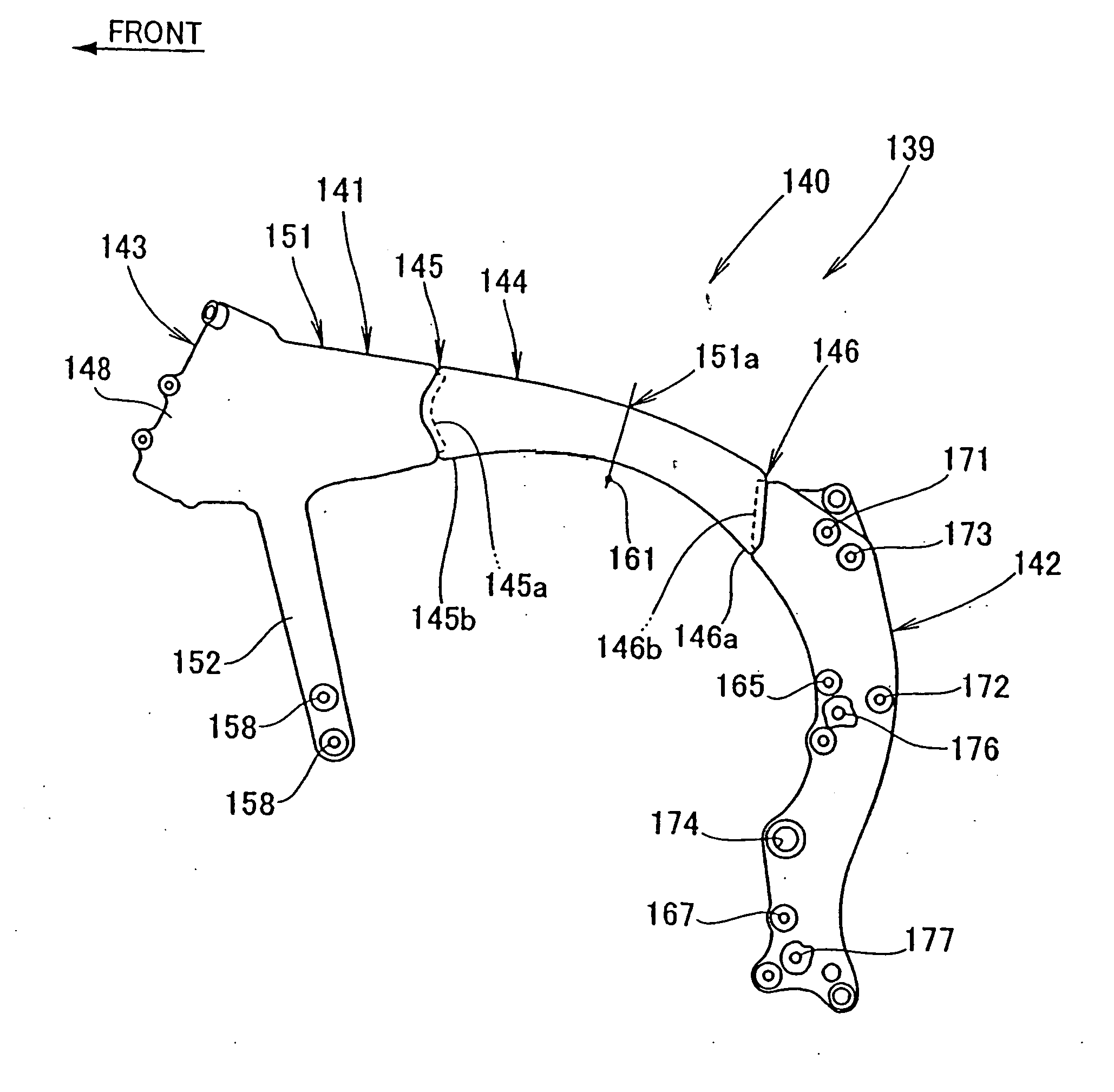
[0080]FIG. 7 is a side view of a main frame 140 according to a second embodiment of the present invention. The main frame 140 of a frame assembly 139 is a member cast from an aluminum alloy and composed of a front frame portion 141, for placement on the front side of the vehicle, and a rear frame portion 142 welded to the rear end of the front frame portion 141.

[0081] The front frame portion 141 is a member formed to be hollow by placing a core within the mold at the time of casting, and is composed of two component parts, i.e., a front half portion 143 and a rear half portion 144 welded to the rear end of the front half portion 143. Incidentally, in FIG. 7, symbol 145 denotes a first coupling portion between the front half portion 143 and the rear half portion 144, and symbol 146 denotes a second coupling portion between the rear half portion 144 and the rear frame portion 142. Thus, the main frame 140 is trisected in the front-rear direction.

[0082] In addition, the front half po...

third embodiment

[0090] FIGS. 8(a) and 8(b) are side views of a main frame 180 according to a third embodiment of the present invention. In FIGS. 8(a) and 8(b), the same components as those in the second embodiment shown in FIG. 7, where unchanged from the second embodiment, are denoted by the same symbols as used above, and detailed description thereof is omitted.

[0091] In FIG. 8(a), a main frame 180, constituting a frame assembly 179, is cast from an aluminum alloy. The main frame 180 is composed of a front frame portion 181 on the front side of the vehicle, and a rear frame portion 142 welded to the rear end of the front frame portion 181. Incidentally, denotes a welded coupling portion 183 is provided between the front frame portion 181 and the rear frame portion 142. The coupling portion 183 includes a front-side coupling portion 183a. The front-side coupling portion 183a is a recessed portion provided at the rear end of the front frame portion 181. The coupling portion 183 also includes a rea...


PUM


Abstract

A motorcycle body frame includes a main frame including a head pipe for supporting a front suspension at the front end thereof, a single leading frame portion extending rearwardly from the head pipe, and a rear frame portion for supporting a rear wheel suspension. The rear frame portion extends substantially downwardly from a rear part of the leading frame portion. The main frame, cast from an aluminum alloy, includes two component parts arranged front-to-rear. For example, a front frame portion is provided, and a rear frame portion is fixed to the rear side of the front frame portion. The leading frame portion has a small section portion, where the main frame is smallest in sectional area, disposed substantially centrally in the longitudinal direction thereof. The two component parts of the frame are joined at a coupling portion of the main frame situated in back of the small section portion.

Description

CROSS-REFERENCE TO RELATED APPLICATIONS [0001] The present invention claims priority under 35 USC 119 based on Japanese patent applications No. 2005-056986, filed on Mar. 2, 2005, and No. 2005-218770 filed on Jul. 28, 2005. The subject matter of each of these priority documents is incorporated by reference herein. BACKGROUND OF THE INVENTION [0002] 1. Field of the Invention [0003] The present invention relates to an improvement in a frame assembly for a motorcycle. [0004] 2. Description of the Background Art [0005] It is well known to form the frame assembly of a motorcycle by casting the frame from an aluminum alloy. It is also well known to provide a single leading frame portion of the motorcycle frame assembly which extends rearwardly from a head pipe. Such a frame assembly is disclosed, for example, in Japanese Utility Model Laid-open No. Hei 1-68293. [0006] The following discussion refers to, and uses reference numbers from, the drawings of Japanese Utility Model Laid-open No. ...

Claims


Application Information

Patent Timeline
Patent Type & Authority Applications(United States)
IPC IPC(8): B62K7/00
CPCB62K11/06
Inventor ISHIKAWA, YUZURUTANIGUCHI, MASAYUKIHASEGAWA, KENJINAKAJIMA, SHUNICHISHIMOKAWA, KOJIHOSHI, NORIO
Owner HONDA MOTOR CO LTD
Why Eureka
Try Eureka