Device for converting a transmitted signal into a digital signal

Inactive Publication Date: 2006-09-07
ALCATEL LUCENT SAS
View PDF4 Cites 50 Cited by
  • Summary
  • Abstract
  • Description
  • Claims
  • Application Information

AI Technical Summary

Benefits of technology

[0023] The present invention aims to improve the reliability of such devices for converting into a digital signal a transmitted signal corresponding to encoded digital data, in particular for encoding in which pulses may occupy only a fract

Problems solved by technology

Now, for relatively high data rates, and in particular for encoding in which the corresponding transmitted signals feature pulses occupying only a fraction of the bit period, the time error margin Δt may be relatively high compared to the width of the pulses of the transmitted signal 12, which leads to a significant probability of error.
Similarly, the predetermined time t0(j) and the k−1 threshold parameters are

Method used


Image

  • Device for converting a transmitted signal into a digital signal
  • Device for converting a transmitted signal into a digital signal
  • Device for converting a transmitted signal into a digital signal

Examples


Embodiment Construction

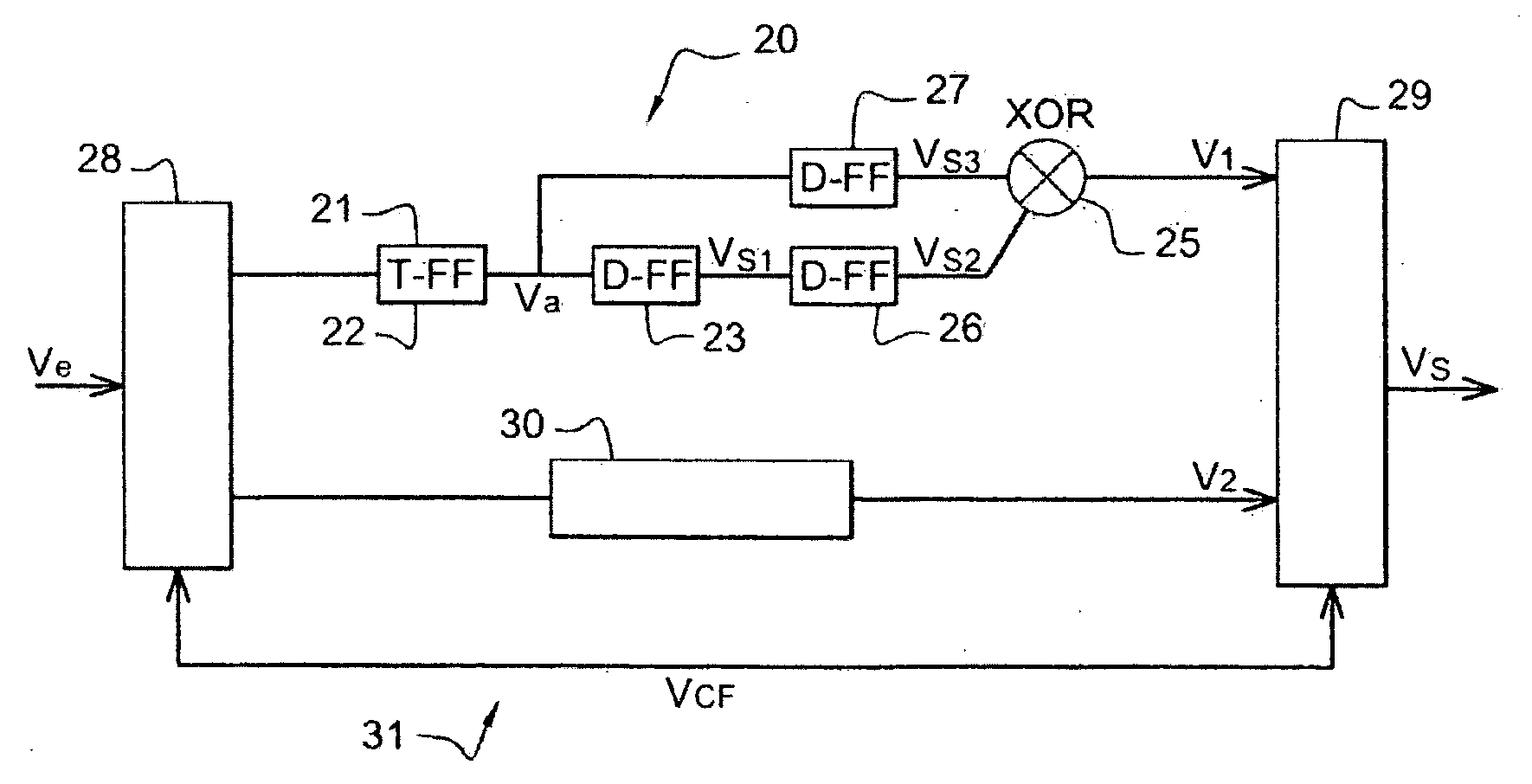
[0072] The preferred embodiment of the converter of the present invention shown in FIG. 2 converts into a digital signal a signal transmitted in baseband over an optical fiber and corresponding to RZ encoded digital data with two states. The transmitted signal VRZ is an electrical signal whose voltage is modulated and which is processed by a photodiode, not shown, and an amplifier, also not shown, for example.

[0073] The converter 20 comprises asynchronous comparison means 21, for example a comparator, for comparing the voltage of the transmitted signal VRZ to a threshold voltage V0. The compared signal Vcmp, which is not shown in FIG. 3 but represents the difference between the voltage levels of the transmitted signal VRZ and the threshold voltage V0, is sent to an input of a two-state machine 22, here a T flip-flop.

[0074] The T flip-flop 22 supplies an asynchronous signal Va with two discrete states and toggles from one state to the other on rising edges of the compared signal Vc...


PUM


Abstract

A device for converting a signal (VRZ) transmitted over a communications channel into a digital signal. The transmitted signal corresponds to encoded digital data with n states, n being at least equal to two. The converter comprises means for asynchronously comparing (21) at least one parameter of the transmitted signal to at least one threshold parameter (V0), an n-state machine (22) for forming at least one signal with at least two states (Va) from at least one compared signal (Vcmp) at the output of the asynchronous comparison means, and means (23, 24, 25) for synchronously detecting changes of state for generating the digital signal from said at least one signal with at least two states and from a recovered clock signal (VCLK).

Description

BACKGROUND OF THE INVENTION [0001] The present invention relates to the field of digital transmission. To be more precise, the present invention relates to the field of converting into a digital signal a signal transmitted over a communications channel and corresponding to digital data encoded on n states. [0002] When information is to be transmitted over a communications channel, for example an electric wire, an optical cable, or a waveguide, or by radio waves, the information is converted into a transmission signal compatible with transmission characteristics of the channel, for example the bandwidth of the channel. [0003] Its conversion into a transmission signal conventionally also comprises an encoding step in which the digital data is encoded in the form of a digital signal with n states, n being at not less than two. That signal is called the encoded signal. [0004] The encoded signal comprises a sequence of synchronized symbols at the timing rate of a clock, each symbol being...

Claims


Application Information

Patent Timeline
IPC IPC(8): H04L27/20
CPCG11B20/1403H03M5/145H04L7/0087H04L7/027
Inventor GODIN, JEAN
Owner ALCATEL LUCENT SAS
Why Eureka
Try Eureka