
Bit error rate performance estimation and control

a transmission system and bit error rate technology, applied in the direction of transmission, link quality based transmission modification, instruments, etc., can solve the problems of untrustworthy equipment vendors, cumbersome maintenance of reliable and robust control, confusion or statistically incorrect decisions, etc., to optimise system performance, prolong the useful life of equipmen

Inactive Publication Date: 2006-09-07
XTERA COMM
View PDF5 Cites 24 Cited by
  • Summary
  • Abstract
  • Description
  • Claims
  • Application Information

AI Technical Summary

Benefits of technology

[0011] Preferably, the predetermined number of bit errors is at least 10. More preferably, the predetermined number is at least 100. Of course, a higher predetermined number will yield a BER to a higher degree of confidence and accuracy, but at the expense of an increased measurement time period.
[0012] The method may be applied to the signal in a continuous manner so that measurement time periods are consecutive. In this way, as soon as the predetermined number of bit errors has been counted the process is repeated to count the subsequent predetermined number of bit errors. Alternatively, when error rates are high, BER may be calculated on a periodic basis as long as the predetermined number of bit errors has been counted in the period and the period is such that the resulting frequency of BER measures is suitable for proper functioning of the control loop.
[0022] As described above, the present invention provides a simple robust measure of the bit error performance of a transmission system and a scheme for the dynamic self-optimisation of the system, which employs a feedback control loop that makes decisions in dependence on the calculated BER performance measure and attempts to minimise the BER. Thus, in contrast to some known schemes, the BER-based feedback technique may be retrofitted to legacy systems without requiring a factory-based set up or calibration procedure.
[0029] Preferably, the system parameter adjusting means comprises a control loop implementing a control algorithm. In this way feedback may be applied within the system. The control loop will preferably adjust the system parameter to minimise the measured BER.
[0034] The system of the present invention employs BER-based feedback applied via a high-level control loop to optimise system performance. System performance is optimised by minimising the BER as computed from a statistically reliable measure of BER performance. Feedback in conjunction with a control loop is self-regulating and so the bit error control system will operate faster at higher error rates and slower at lower error rates, thus automatically compensating for the needs of the system. Furthermore, the dynamic nature of the compensation allows the system to adapt as components in the transmitter and receiver module age, thereby extending their useful lifetime.

Problems solved by technology

These control loops often rely on bit error rate (BER) feedback from the receiver at the end of the transmission system and it can be cumbersome to maintain reliable and robust control.
Existing control loop designs are often simplistic and become confused or make statistically incorrect decisions under certain circumstances.
Many legacy equipment vendors do not trust them and often disable the function once a system is commissioned.
This will eventually lead to degraded system performance, requiring a periodic re-tuning of the system parameters, and offers less overall margin within the system.
However, such estimation techniques are not sufficiently consistent and, when used for feedback control of transmission system parameters, can lead to inappropriate decisions that move the system away from the optimum operating conditions.

Method used


Image

  • Bit error rate performance estimation and control
  • Bit error rate performance estimation and control
  • Bit error rate performance estimation and control

Examples


Embodiment Construction

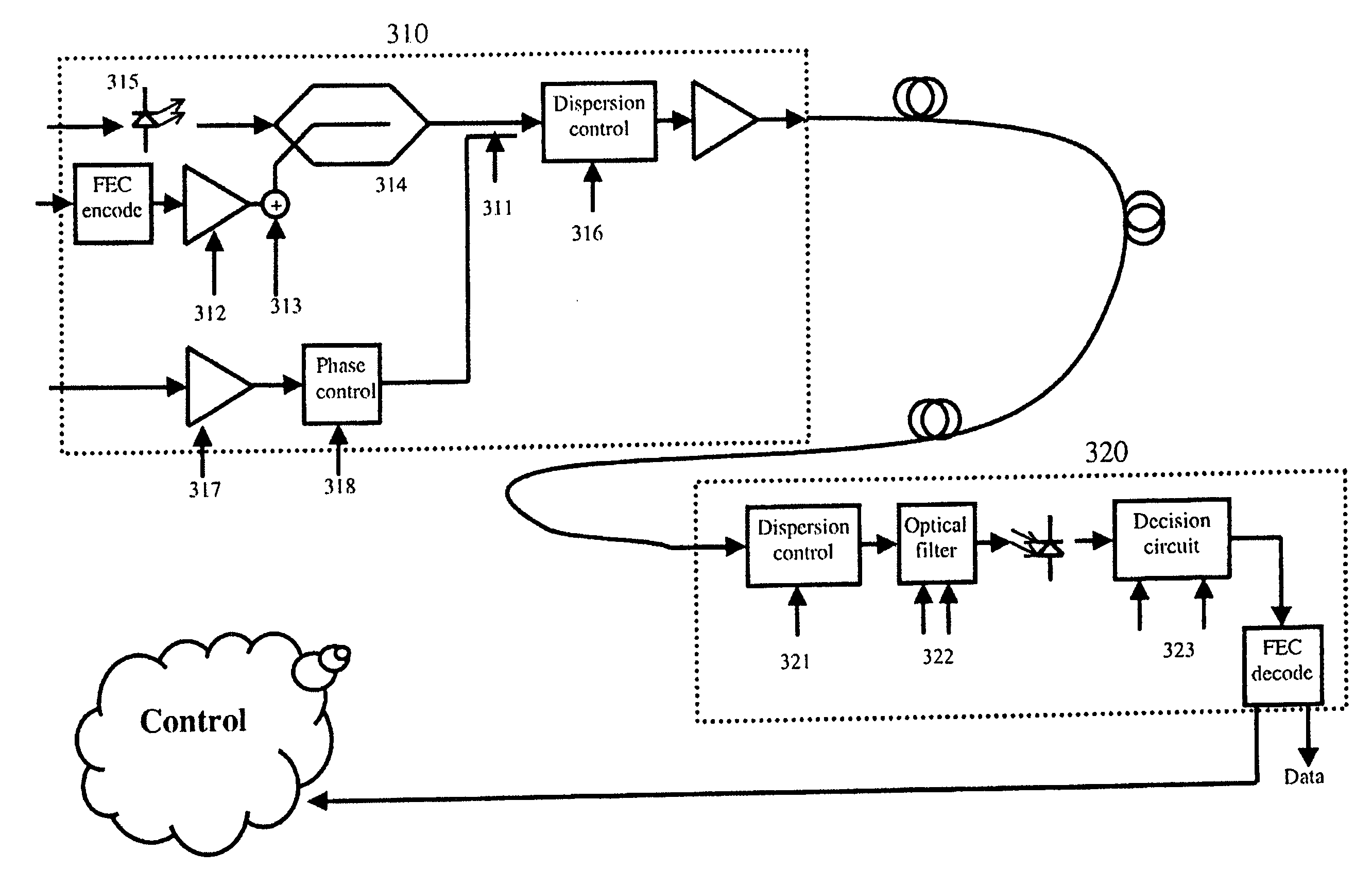
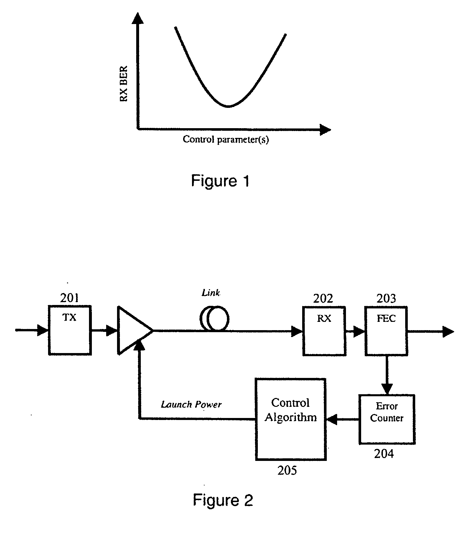
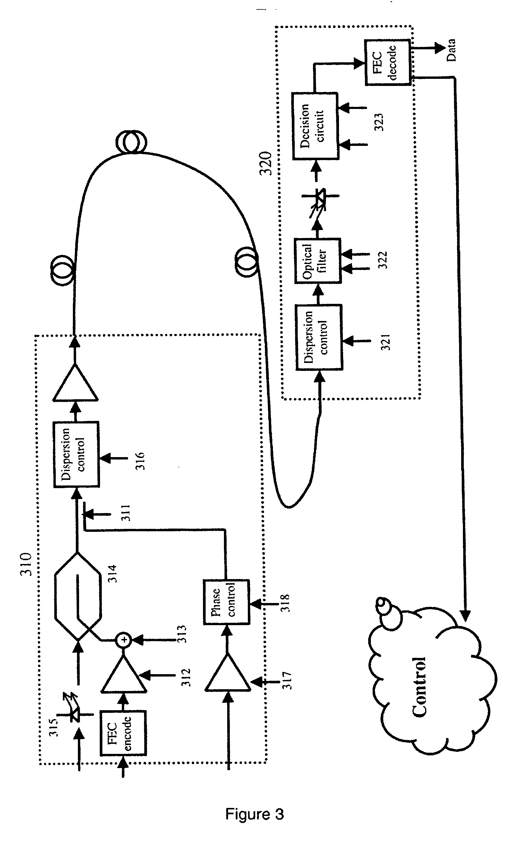
[0043] BER measurement is now generally available as a by-product of forward error correction (FEC) in transponder design, and control loops may be designed to utilise this information to optimise transmission. FIG. 1 illustrates a typical optimisation curve for BER at the receiver (Rx) end as a function of the parameter under control. By appropriate adjustment, the system may be tuned to a local minimum in the BER of the received signal.

[0044] Typically, BER is derived from an error counter register that may periodically be read and re-set. A simplistic algorithm may take this error counter reading at equal time intervals and derive a BER from the relationship BER=Number of Errors / Data Rate. For example, 10 errors in a 1 second period equates to a 1×10⁻⁹ BER for a 10 Gb / s data rate.

[0045] The algorithm may then adjust some parameter of the transmission system to try to improve the BER using a classical dither algorithm. An example of a typical simple algorithm is as follows:

[004...


PUM


Abstract

There is provided a method and system for obtaining an enhanced estimate of bit error rate performance. A receiver module counts a predetermined number of bit errors and concurrently measures the time taken for the predetermined number of bit errors to occur. In this way an estimate of the bit error rate (BER) is obtained which has the same statistical weight regardless of the numerical value of the BER. The estimate of BER can subsequently be used to optimise the parameters of the system such that the true value of BER is at a minimum.

Description

FIELD OF THE INVENTION [0001] The present invention relates to a method for estimating bit error rate (BER) performance of transmission system and its use in applying statistically consistent feedback via a high-level control loop. BACKGROUND TO THE INVENTION [0002] High-level adaptive control loops may be implemented to improve transmission on long haul optical systems. Typically many parameters may be adjusted and each will have an effect that may improve or degrade transmission depending on their adjustment direction. For example, in systems that employ wavelength-division multiplexing (WDM), relative channel powers may be adjusted to equalise channel performance. [0003] These control loops often rely on bit error rate (BER) feedback from the receiver at the end of the transmission system and it can be cumbersome to maintain reliable and robust control. Existing control loop designs are often simplistic and become confused or make statistically incorrect decisions under certain c...

Claims


Application Information

Patent Timeline
Patent Type & Authority Applications(United States)
IPC IPC(8): G06F11/00
CPCH04J14/02H04L1/203H04L1/004H04J14/0221H04L1/0001H03M13/03H04J3/085
Inventor WEBB, STEPHEN MICHAELWINTERBURN, DAVIDDESBRUSLAIS, STEPHEN
Owner XTERA COMM
Learn More