Engine component having a honeycomb structure

a technology of internal combustion engine and honeycomb structure, which is applied in the direction of combustion engine, machine/engine, fuel air intake, etc., can solve the problem that the component cannot be excited at its natural frequency to amplify vibration and noise, and achieve the effect of not absorbing much vibration and noise and being easy to excited

Inactive Publication Date: 2006-09-14
MANN HUMMEL GMBH
View PDF11 Cites 14 Cited by
  • Summary
  • Abstract
  • Description
  • Claims
  • Application Information

AI Technical Summary

Benefits of technology

[0004] How much of the generated noise and vibration is transmitted (or absorbed) by a component of the engine system depends to a large extent on the material and configuration of the component. Applicant noticed that a thin plate-like component, such as a cover or a thin wall of an engine manifold, cannot absorb much vibration and noise. Applicant also noticed that, since a thin plate-like component generally does not have much damping and its natural frequencies are within the frequency range of the generated vibration and noise, it can be easily excited at its natural frequencies. As a result, the noise and vibration is actually amplified by the component.
[0005] Applicant discovered that when a thin plate-like component of an engine system is reinforced with a honeycomb structure, the amount of vibration and noise transmitted through the component can be significantly reduced. In particular, the air trapped in the honeycomb structure functions as a noise insulator, resulting in a significant reduction in the amount of noise transmitted through the component. Additionally, the component can no longer be excited at its natural frequencies to amplify the vibration and noise because its natural frequencies have been moved outside of the frequency range of the generated vibration and noise. Further, the stiffness of the component can be increased without a corresponding increase in material or weight. The term “honeycomb structure” is a known and well-understood term in structural engineering which refers to a structure formed with hollow, thin-walled cells or cavities, especially hexagonal cells. The cells or cavities of the honeycomb structure of the invention are preferably generally hexagonal, but need not be strictly so, and other hollow cellular configurations can be envisioned within the scope of the invention, e.g., diamond-shaped cells.

Problems solved by technology

Additionally, the component can no longer be excited at its natural frequencies to amplify the vibration and noise because its natural frequencies have been moved outside of the frequency range of the generated vibration and noise.

Method used


Image

  • Engine component having a honeycomb structure
  • Engine component having a honeycomb structure
  • Engine component having a honeycomb structure

Examples


Embodiment Construction

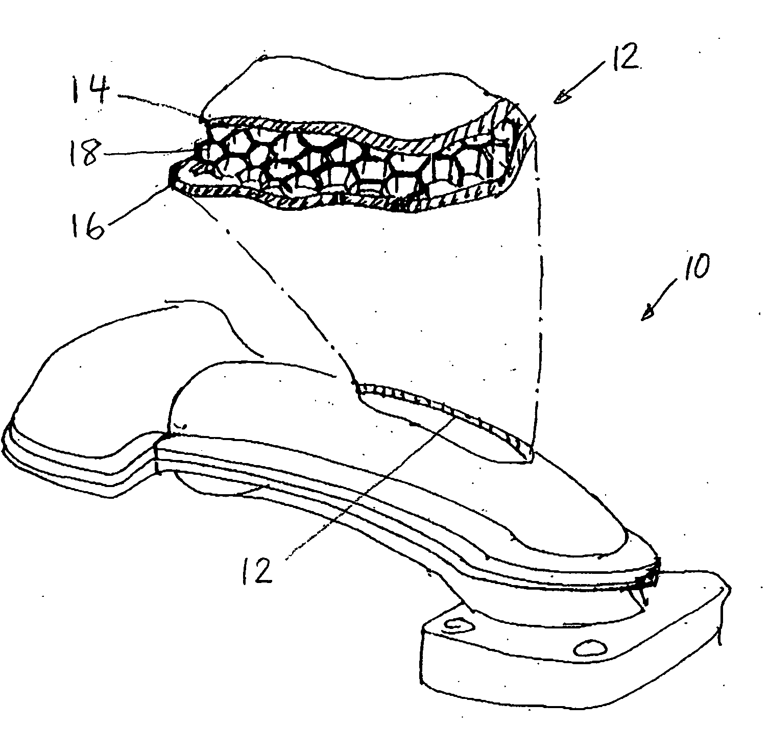
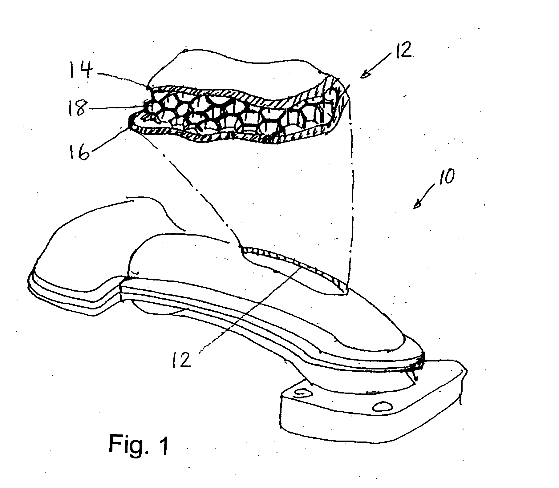
[0010]FIG. 1 illustrates a component 10 of a reciprocating internal combustion engine system (not shown in further detail), which in this case is an engine intake manifold. The intake manifold 10 has a wall 12 that includes an outer layer 14, an inner layer 16, and another layer 18 disposed between the outer and inner layers 14, 16.

[0011] Although the wall 12 of the manifold 10 shown in FIG. 1 is an exterior wall, it may be an interior wall. Each of the layers 14, 16, 18 may be made from any suitable material. For example, each layer 14, 16, 18 can be made from a metallic, plastic or composite material. Examples of suitable materials include metals such as aluminum, synthetic resins such as polyamide (nylon), polystyrene and / or acrylic resins, and well known composite materials such as carbon fiber composites.

[0012] The honeycomb layer 18 preferably is attached to the inner and outer layers 14, 16 and may be attached to the inner and outer layers 14, 16 in any suitable manner. For...


PUM

PropertyMeasurementUnit
adhesiveaaaaaaaaaa
structureaaaaaaaaaa
cellular structureaaaaaaaaaa

Abstract

A component of a reciprocating internal combustion engine system includes first, second, and third layers. The third layer has a honeycomb structure and is disposed between the first and second layers.

Description

FIELD OF THE INVENTION [0001] The present invention relates to a reciprocating internal combustion engine component that has a honeycomb structure. BACKGROUND OF THE INVENTION [0002] It is highly desirable to reduce the noise and vibration generated by a motor vehicle, in particular by a passenger car. In a motor vehicle with an internal combustion engine, the engine system, including the reciprocating internal combustion engine and its accessory parts, is a major source of vibration and noise. A portion of the noise and vibration generated by the reciprocating internal combustion engine system is transmitted through the components of the engine system to the ambient environment and to the other components of the vehicle. The rest of the generated noise and vibration is absorbed by the components of the engine system. [0003] It has been known in the past to wrap some jet aircraft engine components in with a covering having a cellular structure to reduce noise. Such coverings, howeve...

Claims


Application Information

Patent Timeline
Patent Type & Authority Applications(United States)
IPC IPC(8): F02M35/10F02B77/00
CPCF02B77/13F02M35/10072F02M35/10321F02M35/10327F02M35/10334F02M35/10347F02M35/10354F02M35/1036F02M35/104F02M35/1272F02M35/1277F02M35/1283
Inventor VICHINSKY, KEVIN
Owner MANN HUMMEL GMBH
Why Eureka
Try Eureka