Radiation detectors

a detector and radiation technology, applied in the field of radiation detectors, can solve the problems of difficult to locate the band gap analytically, crystals, and measurement of electron positions, and achieve the effects of improving volumetric image, improving spatial resolution, and thinning the sli

Inactive Publication Date: 2006-09-14
SUHAMI AVRAHAM
View PDF1 Cites 160 Cited by
  • Summary
  • Abstract
  • Description
  • Claims
  • Application Information

AI Technical Summary

Benefits of technology

[0179] CT scanners may use the pixellated, but without walls, thick PBCS radiation detectors, enabling thinner slices and higher spatial resolutions, both leading to better volumetric images.
[0180] Digital X-ray radiography may also benefit from the virtual pixellation of the thick PBCS radiation detector structure that allows full absorption at high X-ray energies, while achieving an order magnitude better spatial resolutions than the current technology.
[0181] The implications of PBCS Compton cameras for Homeland Security applications are dramatic. Detecting the direction of the γ rays enables Tomographic imaging and discards the non-directional background, while real time Dynamic imaging, differentiates a “moving source” from all static sources of background: The ability to subtract background without shielding and collimation enables a lightweight portable radiation camera that multiplies its deployment areas.

Problems solved by technology

As actual photonic crystals are complex structures, in general it is hard to locate the bandgaps analytically.
These crystals, though, cannot confine electromagnetic radiation in the third dimension, due to the “leaking” of the transverse electromagnetic waves into the 3rd dimension.
The practical obstacles are the measurement of the electron's position before the scattering and the direction of its recoil after interaction with the incoming gamma ray.
Gamma cameras with straight tubular collimators give a 2D projection of the radionuclide distribution, on the surface of the camera and cannot give depth information.

Method used


Image

  • Radiation detectors
  • Radiation detectors
  • Radiation detectors

Examples


Embodiment Construction

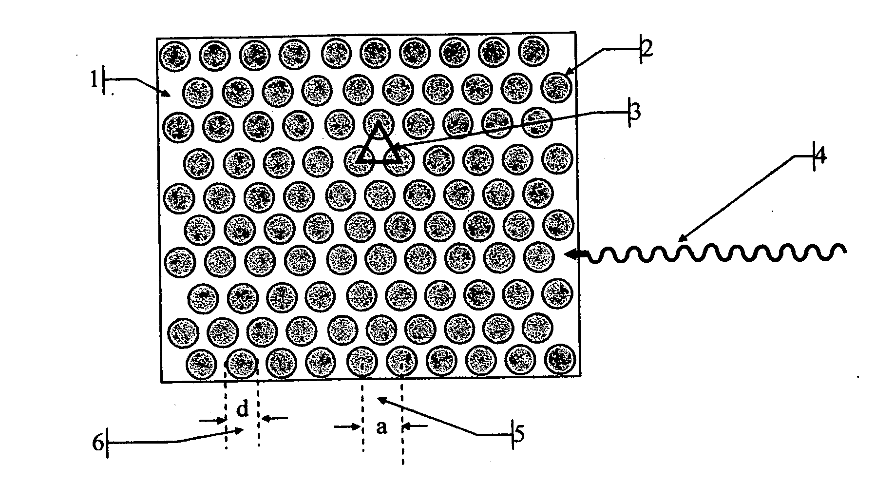
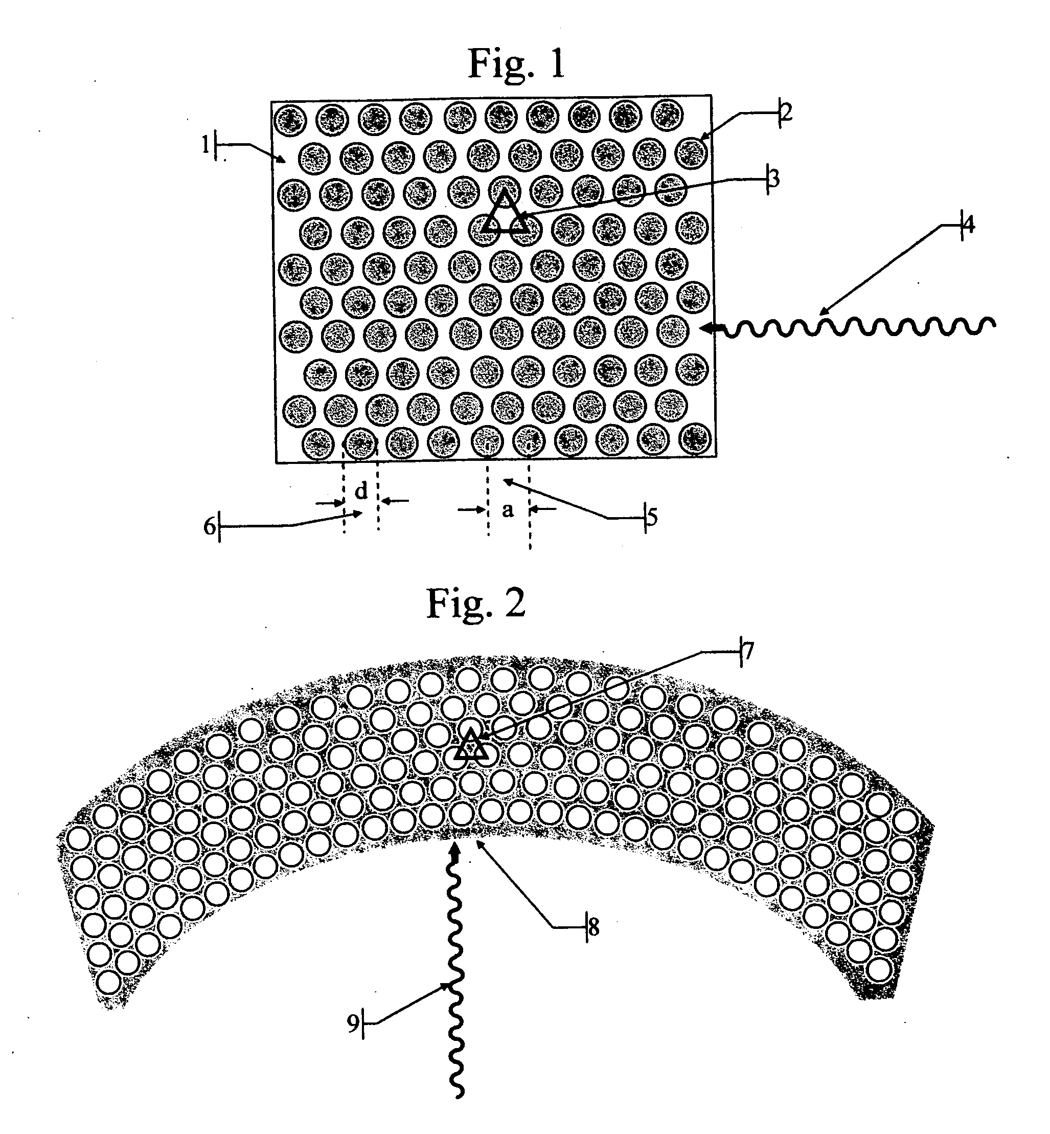
[0230]FIG. 1 illustrates a triangular periodic lattice of a 2 dimensional Photonic Bandgap Crystal Scintillator (PBCS) viewed from above. The structure may be interpreted as holes 2 (n0=1) in a high index matrix 1, for example in a CsI scintillator (n1=1.95) or as pillars 2 separated by air or aerogel.

[0231] The lateral dimensions of the columns or holes (d) 6 and the distance (a) 5 between them, together with their respective dielectric constants determine the behavior of such structures in respect to the propagation of electromagnetic radiation across the 2D plane. From an extrapolation of the behavior of one dimensional Bragg gratings, we can guess that destructive interference in two dimensional lattices too, will occur for approximately half-wavelength interference for distances between the holes (or columns) forming the lattice. As an incoming beam 4 will be refracted from each layer of columns (or holes), the distances it travels between successive refractions changes; as a ...


PUM


Abstract

The invention consists in structuring scintillation radiation detectors as Photonic Bandgap Crystals or 3D layers of thin filaments, thus enabling extremely high spatial resolutions and achieving virtual voxellation of the radiation detector without physical separating walls. The ability to precisely measure the recoil electron track in a Compton camera enables to assess the directions of the gamma rays hitting the detector and consequently dispensing with collimators that strongly reduce the intensity of radiation detected by gamma cameras. The invention enables great enhancements of the capabilities of gamma cameras, SPECT, PET, CT and DR machines as well as their use in Homeland Security applications. Methods of fabrication of such radiation detectors are decribed.

Description

[0001] This provisional application claims the benefit of the filing of U.S. Provisional Patent Application Ser. No. 60 / 660,836 filed on Mar. 14, 2005 Titled: Photonic Bandgap scintillator crystals and U.S. Provisional Patent Application Ser. No. 60 / 703,149 filed on Jul. 29, 2005FIELD OF THE INVENTION [0002] This invention relates to radiation detectors RELEVANT PATENTS [0003] The patents below are incorporated in this application by reference. [0004] U.S. Pat. No. 6,903,873 High omnidirectional reflector Joannopoulos, et al. [0005] U.S. Pat. No. 6,906,559 Method and apparatus for gamma ray detection by Tümer; Tümay O. [0006] U.S. Pat. No. 6,898,265 Scintillator arrays for radiation detectors and methods of manufacture by Mliner et al. [0007] U.S. Pat. No. 6,892,011 Method and apparatus for fabrication of plastic fiber optic block materials and large flat panel displays by Walker, et al. [0008] U.S. Pat. No. 6,881,959 Method and system for generating an image of the radiation densit...

Claims


Application Information

Patent Timeline
Patent Type & Authority Applications(United States)
IPC IPC(8): G01T1/20
CPCB82Y20/00G01T1/1644G01T1/201A61B6/037G01T1/2985G02B6/1225G01T1/202
Inventor SUHAMI, AVRAHAM
Owner SUHAMI AVRAHAM
Why Eureka
Try Eureka