Multi-channel fluorescence measuring optical system and multi-channel fluorescence sample analyzer

a fluorescence sample and optical system technology, applied in the direction of optical radiation measurement, luminescent dosimeters, instruments, etc., can solve the problems of increasing the volume and manufacturing cost of the apparatus, increasing the manufacturing cost of the multi-channel sample analyzer, and not being suitable for a small analyzer

Active Publication Date: 2006-09-14
SAMSUNG ELECTRONICS CO LTD
View PDF11 Cites 37 Cited by
  • Summary
  • Abstract
  • Description
  • Claims
  • Application Information

AI Technical Summary

Benefits of technology

[0012] The present invention provides a small, cheap multi-channel fluorescence measuring optical system which can rapidly detect fluorescence samples cont

Problems solved by technology

However, when using as many detecting units as there are samples, the same number of photodetectors, filters, etc., as the samples are required, thereby increasing the volume and the manufacturing cost of the apparatus.
However, since the highly sensitive CCD needed for fluorescence analysis is expensive, the manufacturing cost of the multi-channel sample analyzer is increased, and thus the analyzer using the CCD detector is not suitable for a small analyzer.
However, due to the limit of the frame rate (the number of frame capt

Method used


Image

  • Multi-channel fluorescence measuring optical system and multi-channel fluorescence sample analyzer
  • Multi-channel fluorescence measuring optical system and multi-channel fluorescence sample analyzer
  • Multi-channel fluorescence measuring optical system and multi-channel fluorescence sample analyzer

Examples


Embodiment Construction

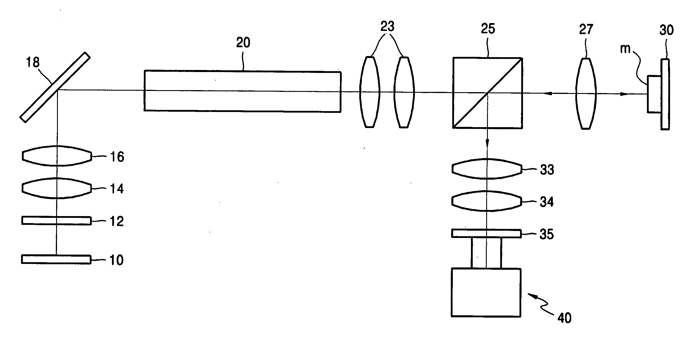
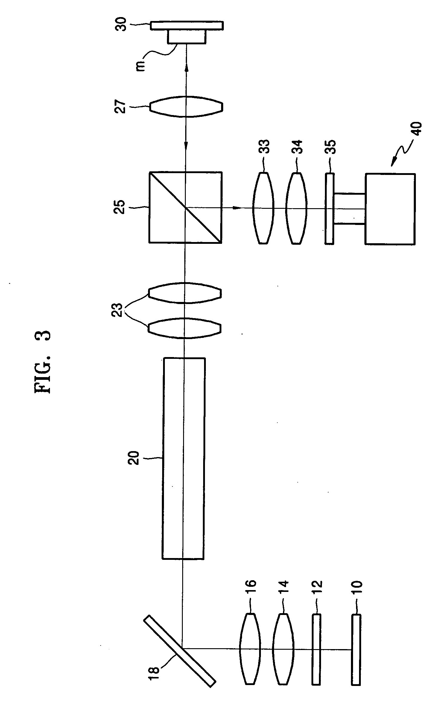
[0035] Referring to FIG. 3, a multi-channel fluorescence measuring optical system according to an embodiment of the present invention includes a light source 10, an integrator 20 for making the light from the light source have a uniform intensity distribution, a sample holder 30 for mounting at least one sample (m) which reacts to the light passing through the integrator 20, and a light detecting unit 40 for detecting the fluorescence emitted from the sample (m). A beam splitter 25 is provided on the optical path between the integrator 20 and the sample holder 30, for transmitting a portion of the incident light and reflecting the other to divide the incident light in a predetermined ratio. A portion of the light transmitted through the integrator 20 is transmitted through the beam splitter 25 to strike the sample (m), and the rest of the light is reflected at the beam splitter.

[0036] The fluorescence emitted from the sample (m) is reflected by the beam splitter 25 and directed to ...


PUM


Abstract

A multi-channel fluorescence measuring optical system and a multi-channel fluorescence sample analyzer using the optical system are provided. The multi-channel fluorescence measuring optical system, which irradiates light onto a plurality of sample channels and detecting fluorescence radiated from samples, includes: a light source; an integrator for giving the light irradiated from the light source a uniform intensity distribution; a sample holder having a plurality of sample channels on which the samples are mounted, wherein the samples are exited by the light emitted from the integrator; and a beam splitter between the integrator and the sample holder for dividing the incident light in a predetermined ratio. Since the light intensities of fluorescence images are detected using optical fiber bundles and photodiodes, the manufacturing cost can be greatly reduced, and the optical system can be miniaturized.

Description

CROSS-REFERENCE TO RELATED PATENT APPLICATION [0001] This application claims the benefit of Korean Patent Application No. 10-2005-0010186, filed on Feb. 3, 2005, in the Korean Intellectual Property Office, the disclosure of which is incorporated herein in its entirety by reference. BACKGROUND OF THE INVENTION [0002] 1. Field of the Invention [0003] The present invention relates to a multi-channel fluorescence measuring optical system and a multi-channel fluorescence sample analyzer, and more particularly, to a small, cheap multi-channel fluorescence measuring optical system which can rapidly detect fluorescence samples contained in a multi-channel sample holder having several micro-fluidic channels using one optical system, and a multi-channel fluorescence sample analyzer using the optical system. [0004] 2. Description of the Related Art [0005] A widely known method of analyzing a sample is to irradiate the sample with a specific wavelength of light and detect the spectrum of light ...

Claims


Application Information

Patent Timeline
IPC IPC(8): G01J1/58F21V9/16
CPCG01J3/02G01J3/0218G01J3/0256G01J3/10G01J3/4406G01J2003/1213G01N21/05G01N21/6452G01N21/6456G01N2021/3174G01N2021/6419G01N2021/6421G01N2021/6471G01N2021/6484G01N2201/0221G01N2201/0407G01N2201/0461G01N2201/0612G01N2201/0627G01N2201/0631G01N2201/0806G01N2201/0833G01N2021/0346E04H13/005E04H13/006
Inventor OK, GYEONG-SIKKIM, SU-HYEONKIM, JIN-TAEOH, KWANG-WOOK
Owner SAMSUNG ELECTRONICS CO LTD
Why Eureka
Try Eureka