Power conversion and voltage sag correction with regenerative loads

a technology of regenerative load and power conversion system, which is applied in the direction of emergency power supply arrangement, process and machine control, instruments, etc., can solve the problems of power sag and swell, power supply failure, equipment damage, etc., and achieve low cost, high reliability, and high efficiency.

Active Publication Date: 2006-09-14
ROCKWELL AUTOMATION
View PDF15 Cites 54 Cited by
  • Summary
  • Abstract
  • Description
  • Claims
  • Application Information

AI Technical Summary

Benefits of technology

[0005] A power conversion module in accordance with the present invention is capable of supplying AC power to potentially regenerative loads with high efficiency, relatively low cost, and high reliability. The power conversion module may be incorporated in systems utilized in applications such as AC motor drives, power conditioning equipment, including battery storage UPS systems, and dynamic voltage sag correctors with capacitive energy storage. Component size and cost can be minimized in accordance with the invention by utilizing control of the dissipation of regenerative power in a manner which takes advantage of the dynamic performance characteristics of the components utilized for dissipating the regenerative power.
[0006] A power conversion module in accordance with the invention includes a rectifier having rectifying devices connected to receive AC input power from AC input lines and to provide DC power on high and low DC bus lines. First and second energy storage capacitors are connected in series across the DC bus lines. The connection between the capacitors defines a common node to which a DC bus common conducting line is connected. An inverter having inverter switching devices is connected to the DC bus lines to receive power therefrom, and with the inverter switching devices switchable to provide AC output power. A first bus discharge switching device and a discharge resistor are connected in series across the high DC bus line and the common line, and in parallel with the first energy storage capacitor. A second bus discharge switching device and a discharge resistor are connected in series between the common line and the low DC bus line and in parallel with the second energy storage capacitor. A DC bus control circuit is connected to the DC bus lines and the common line to receive the voltage therefrom and is connected to the first and second bus discharge switching devices. The DC bus control circuit selectively turns the first discharge switching device on for a period of time when the voltage between the high DC bus line and the common line exceeds a selected limit and turns the second discharge switching device on for a period of time when the voltage between the low DC bus line and the common line exceeds a selected limit. The turn-on of the first or second discharge switching device thereby discharges the energy storage capacitor to which it is connected to reduce the voltage thereon, so that excessive voltage which might occur across one of the energy storage capacitors is avoided even if the total voltage across the DC bus lines is within acceptable limits. Controlling the voltage separately on the two energy storage capacitors in this manner allows accommodation of any of various types of conditions that might otherwise result in an excessive charging of the storage capacitors, including regenerative power flowing back from a load into the DC bus lines or voltage spikes from the utility power system passed through the rectifier to the DC bus lines.
[0007] During an over-voltage condition on one or both of the energy storage capacitors, the discharge switching device connected to that capacitor preferably switches on and off periodically with a selected duty cycle (ratio of on-time to total time of a period) to discharge energy from the energy storage capacitor through the discharge resistor. The duty cycle and the period of switching can be selected to ensure that the temperature rating of the discharge resistor is never exceeded. The discharge resistor can be sized so that its average power rating can handle the expected maximum regenerative power without damage. If the regenerative power will be applied only for a relatively short duration, as is the case for voltage sag correctors which are intended to operate only intermittently for short periods of several seconds or less, the discharge resistor can absorb energy at a much higher rate initially, when it is at a low temperature, than it is able to absorb on average after it has reached its maximum operating temperature. In accordance with the present invention, it is preferred that the control circuit control the switching of the discharge switching device during an over-voltage condition using a variable duty cycle that is based on the dynamic power dissipation characteristics of the discharge resistor. The variable duty cycle may be determined, for example, by the temperature of a model of the discharge resistor such that the discharge switching device is turned off when the model of the discharge resistor indicates that a high set-point temperature is reached, and is turned on when the model of the discharge resistor indicates that a lower set-point temperature has been reached. Where over-voltage bus conditions due to regenerative loads or power line transient spikes are infrequent and of short duration, as is typically the case for most events compensated by voltage sag correctors, the over-voltage condition can be eliminated more rapidly using lower rated components than would be possible using a fixed duty cycle that was selected to ensure that the average maximum power rating of the discharge resistor was never exceeded. By controlling the discharge of the DC bus in this manner, it is possible to reduce not only the resistor size and cost, but also the size and cost of other components that otherwise would be required to be rated for higher average power dissipation, such as heatsinks for the discharge switching devices, fuses, and the conductors connecting the various components. The use of a variable duty cycle in accordance with the invention will always allow the maximum available power absorption capacity to be utilized. Power conditioning equipment incorporating the invention can be designed to operate up to reasonable selected limits on the frequency and duration of disturbances and to provide component protection outside those limits.

Problems solved by technology

Momentary voltage disturbances such as sags and swells, if not compensated, can result in significant financial losses for industrial power users because of potential shutdown of voltage-sensitive production equipment in the middle of critical processes, with resulting scrap, equipment damage, and lost production.
Voltage sags and swells are a widespread, inherent and inevitable problem in any large-scale power distribution network.
In particular, uninterruptible power supplies (UPS) are widely used and commercially available over a wide range of backup power requirements.
UPS systems offer comprehensive power protection but are also relatively costly and maintenance intensive.
For cost and reliability reasons, most commercial power protection equipment utilizes a rectifier having uncontrolled rectifying devices rather than active switches so that the regenerative power cannot be transferred to the utility power lines.
Conventional battery based UPS systems are often not well suited to handling regenerative loads because batteries generally are limited in the rate at which they can absorb energy.
Some flywheel based UPS products can handle regenerative loads but are also more expensive and bulkier than battery based systems.
This can potentially lead to a DC bus over-voltage condition which requires that the inverter of the device be shut off before damage to the inverter components can occur, with the consequence that sag correction is not available under these regenerative load conditions.
Similar problems are encountered in AC power converters which supply their inverter from a DC bus across which a DC bus capacitor is connected.
This approach to controlling the DC bus under regenerative load conditions requires a relatively high power rated resistor which must be packaged so that it is capable of dissipating a significant amount of heat without affecting other system components, thus increasing the relative cost and size of the overall device.

Method used


Image

  • Power conversion and voltage sag correction with regenerative loads
  • Power conversion and voltage sag correction with regenerative loads
  • Power conversion and voltage sag correction with regenerative loads

Examples


Embodiment Construction

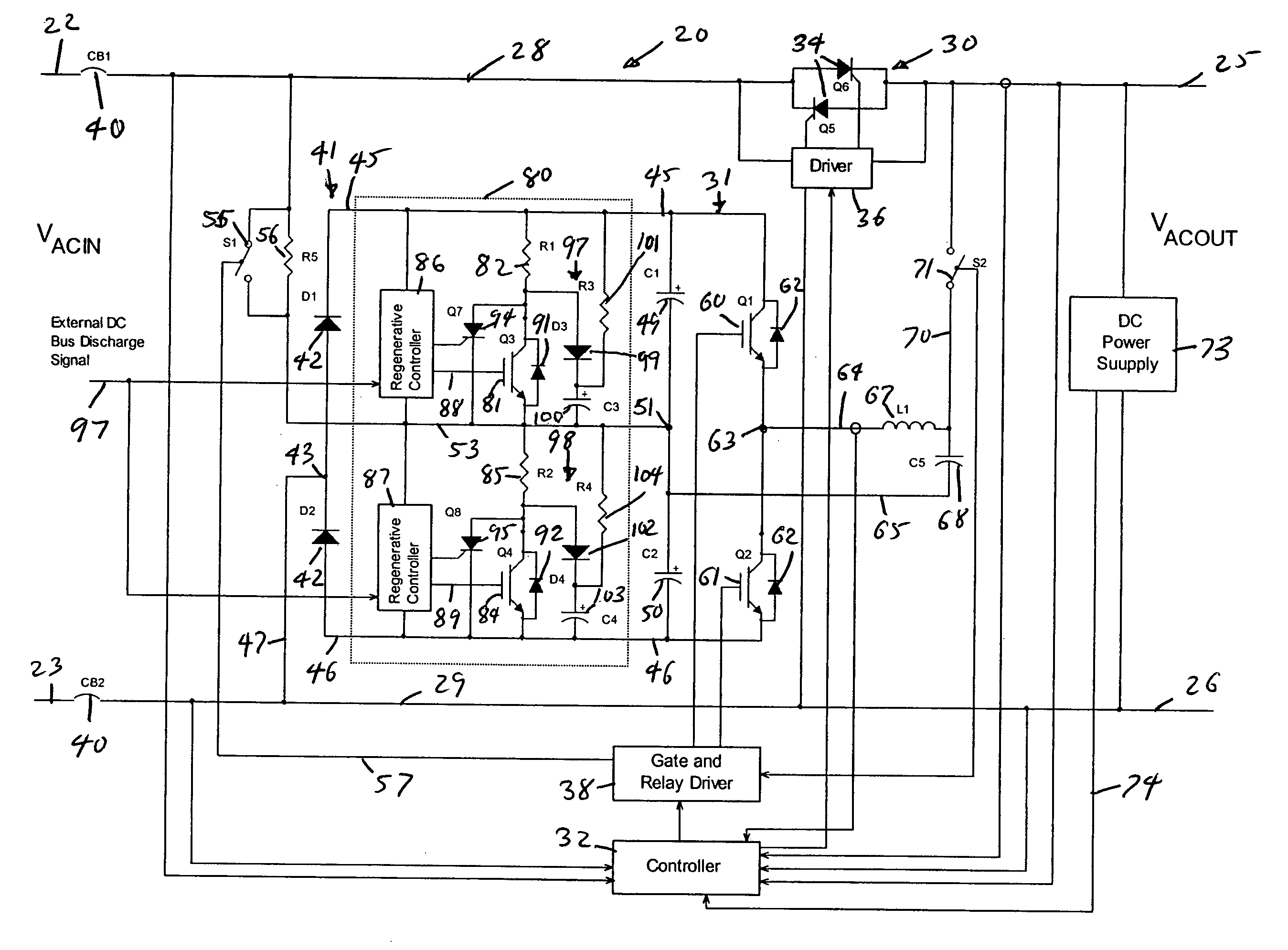
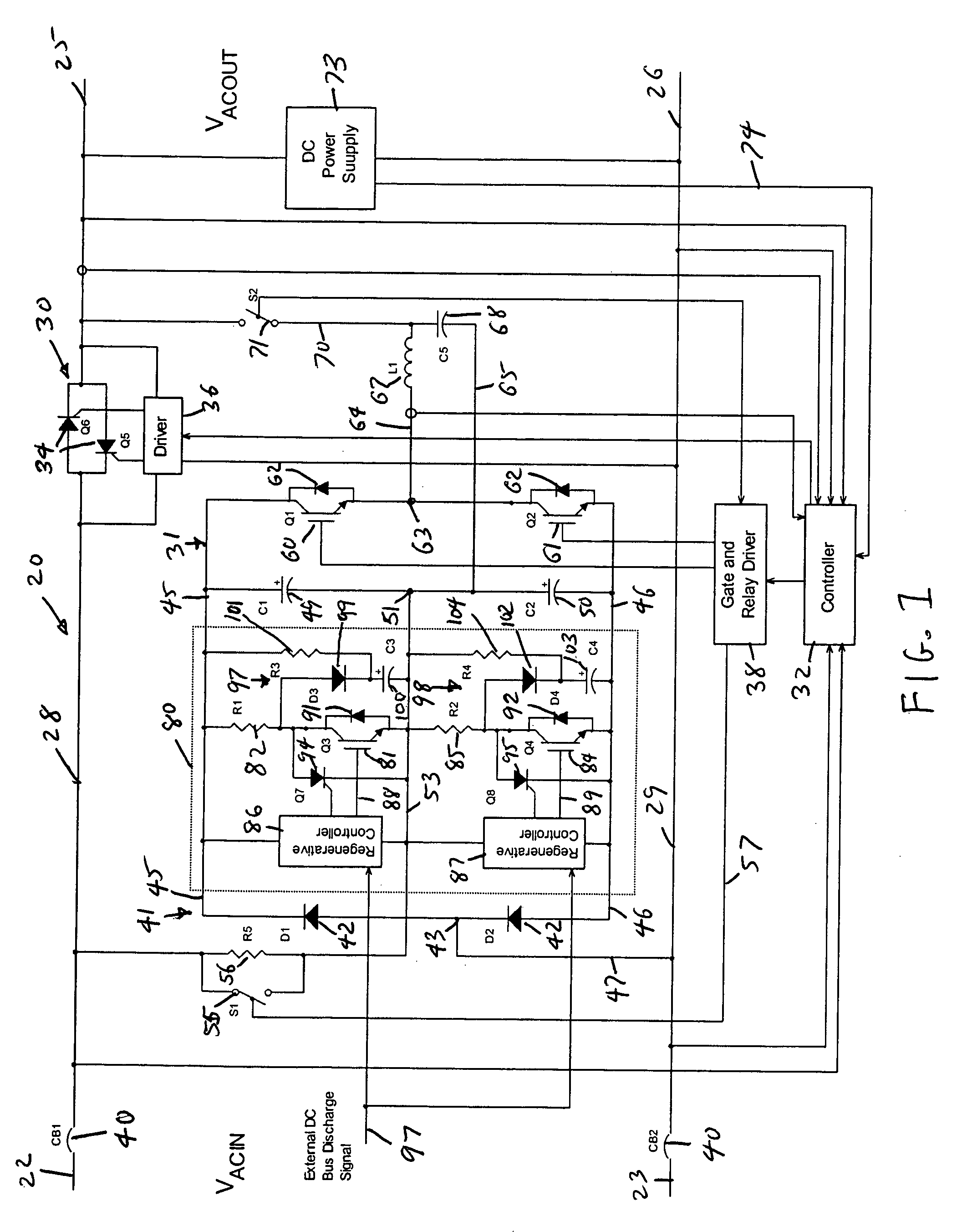
[0014] The present invention may be implemented as a power conversion module capable of supplying AC power to potentially regenerative loads for applications such as motor drives, power conditioning equipment including battery energy storage UPS, and dynamic voltage sag correctors with capacitive energy storage. The present invention is particularly well suited to be incorporated in a dynamic voltage sag corrector having capacitive energy storage to protect against over-voltage conditions that can occur under regenerative load conditions. The present invention will be described below implemented in a dynamic voltage sag corrector, although it is understood that the power conversion module of the invention may be utilized in other applications.

[0015] As shown generally at 20 in FIG. 1, a dynamic voltage sag corrector in accordance with the invention receives AC power at a voltage Vacin from a power source (e.g., utility lines) on AC power input lines 22 and 23, and delivers AC power...


PUM


Abstract

In dynamic voltage sag correctors and other power conversion equipment having a DC bus that is subject to over-voltage conditions due to power being fed back by a regenerative load, a bus discharge switching device and a discharge resistor are connected in series across the DC bus lines. The discharge switching devices are switched on to discharge the energy storage device connected to the bus, or to separately discharge the two capacitors of a split capacitor DC bus, to eliminate the over-voltage conditions. The discharge switching devices may be switched on and off periodically with a selected duty cycle to discharge energy from the energy storage capacitor or other energy storage device through the discharge resistor at a rate which does not exceed the power rating of the discharge resistor. The discharge switching device may be switched with a fixed duty cycle or with a variable duty cycle that is based on the dynamic power dissipation characteristics of the discharge resistor.

Description

FIELD OF THE INVENTION [0001] This invention pertains generally to the field of electrical power supplies and power conversion systems, and particularly to power line conditioning systems for correcting voltage sag and drop conditions. BACKGROUND OF THE INVENTION [0002] Power line conditioning systems are in common use to provide compensation for and correction of voltage sags and drops in the power provided from utility power lines to a critical load. Momentary voltage disturbances such as sags and swells, if not compensated, can result in significant financial losses for industrial power users because of potential shutdown of voltage-sensitive production equipment in the middle of critical processes, with resulting scrap, equipment damage, and lost production. Voltage sags and swells are a widespread, inherent and inevitable problem in any large-scale power distribution network. Various systems and techniques for correcting voltage disturbances have been developed and are commerci...

Claims


Application Information

Patent Timeline
Patent Type & Authority Applications(United States)
IPC IPC(8): H05B41/36
CPCH02J3/1842H02J9/062Y02E40/22Y02E40/20
Inventor SCHNEIDER, ROBERT S.
Owner ROCKWELL AUTOMATION
Why Eureka
Try Eureka