Probe assembly with a light hood and a detecting instrument equipped with the same

a technology of detecting instruments and probe assemblies, which is applied in the field of testing devices, can solve the problems of poor mouth flushing, error in the determination of sample being detected, and light cross interference between, and achieve the effect of facilitating the smooth motion of test cells

Inactive Publication Date: 2006-09-14
BEIJING YUANDE BIO MEDICAL ENG
View PDF9 Cites 7 Cited by
  • Summary
  • Abstract
  • Description
  • Claims
  • Application Information

AI Technical Summary

Benefits of technology

[0030] Preferably, said light hood may have: a middle portion with a reduced diameter forming a annular groove around it, with a clearance between its outer wall and the inner wall of the through-hole of said top plate to form a loose fit between said light hood and said through-hole; a lower outer flange, formed at the lower portion of said light hood, and having its outer contour and size fitting with the inner contour and size of said through-hole of said top plate, and being guided by said through-hole. Since there is a loose fit between said light hood and said through-hole and the length of the lower outer flange used in the guiding is relatively small, the sticking of said light hood during sliding up or down can be avoided.
[0031] Preferably, said light hood may have a lower inner flange opposite to said lower outer flange, both a lower inner circumferential chamfer and a lower outer circumferential chamfer merging with said lower inner circumferential chamfer to form a circumferential tip are formed at the radial outside of the peripheral edge off the lower inner flange bottom surface (a circumferential downward projection with a circumferential tip is formed at the radial outside of the peripheral edge of the lower inner flange bottom surface by a lower inner circumferential chamfer and a lower outer circumferential chamfer), with the area in the radial inside of the bottom surface of said lower inner flange being flat. Such structure facilitates the smooth motion of the test cells in relation to the light hood. With a plurality of test cells placed on the micro-cellular plate, said light hood slides down and up respectively by its gravity and a up pushing force generated when the top of the test cell comes in contact with the chamfers of the lower inner flange of said light hood during the moving the micro-cellular plate with the test cells, and finally the circumferential tip formed by both the chamfers inserts into the joint between the test cell being detected and its adjacent cells, as the tip is aligned with the joint close.

Problems solved by technology

The flush of their mouths is poor and also fluctuations of the height exist among plurality of the test cells, which can cause a light cross interference between the determined samples(namely, a secondary light seal defect).
Said light cross interference refers to that the optical pickup is influenced by the light from the adjacent test cells, leading to an error in the determination of the sample being detected since the top of the test cell being detected or the top of its adjacent test cells can't closely abut against the top plate 102 of the housing due to the poor flush and the fluctuations of the heights of test cells.

Method used


Image

  • Probe assembly with a light hood and a detecting instrument equipped with the same
  • Probe assembly with a light hood and a detecting instrument equipped with the same
  • Probe assembly with a light hood and a detecting instrument equipped with the same

Examples


Embodiment Construction

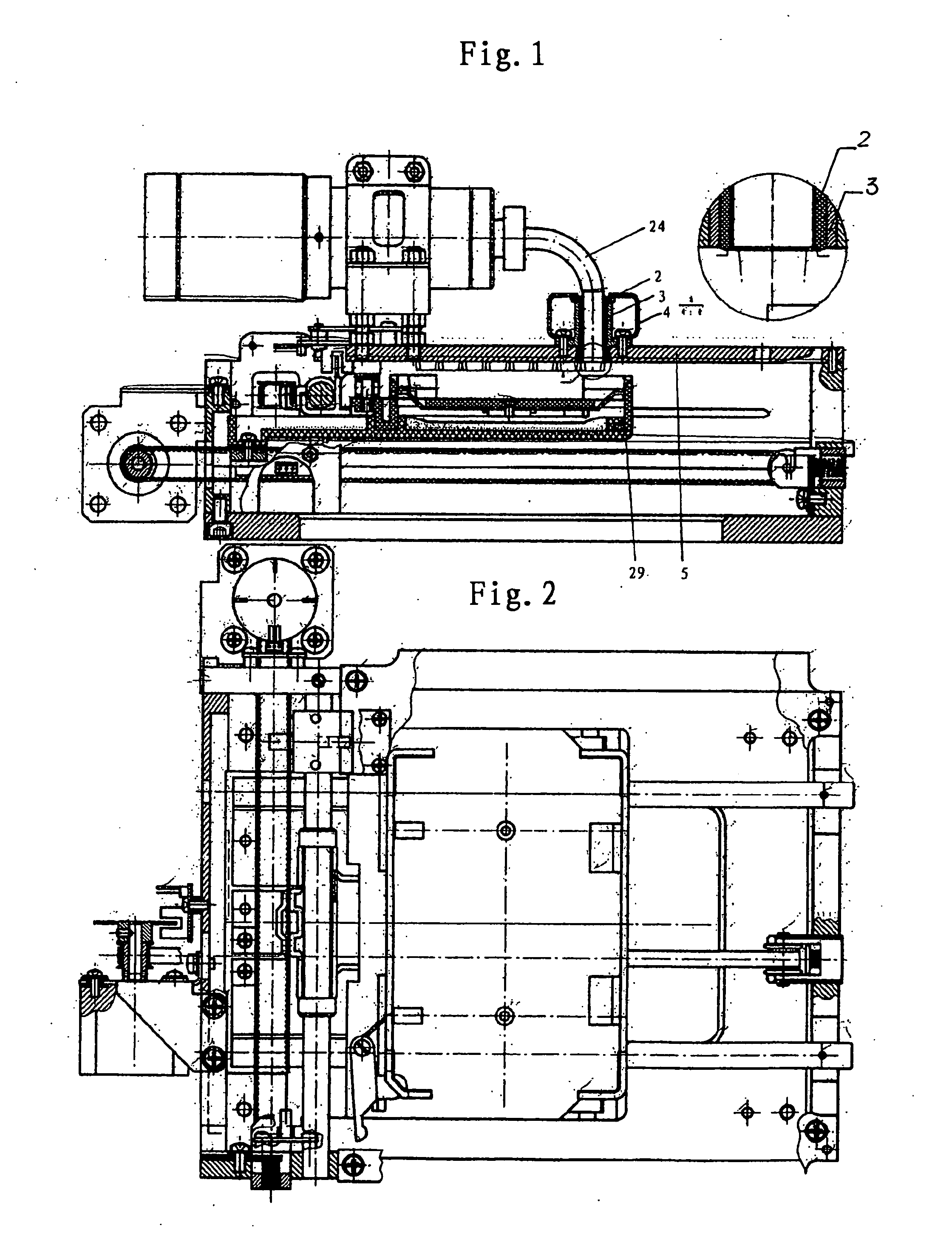
[0072]FIG. 1 and 2 show the micro-single photon counting device according to the preferable embodiment of the present invention, which comprises the probe assembly according to the preferable embodiment of the present invention, as its part. At first, said probe assembly will be described in detail in conjunction with FIG. 3-14.

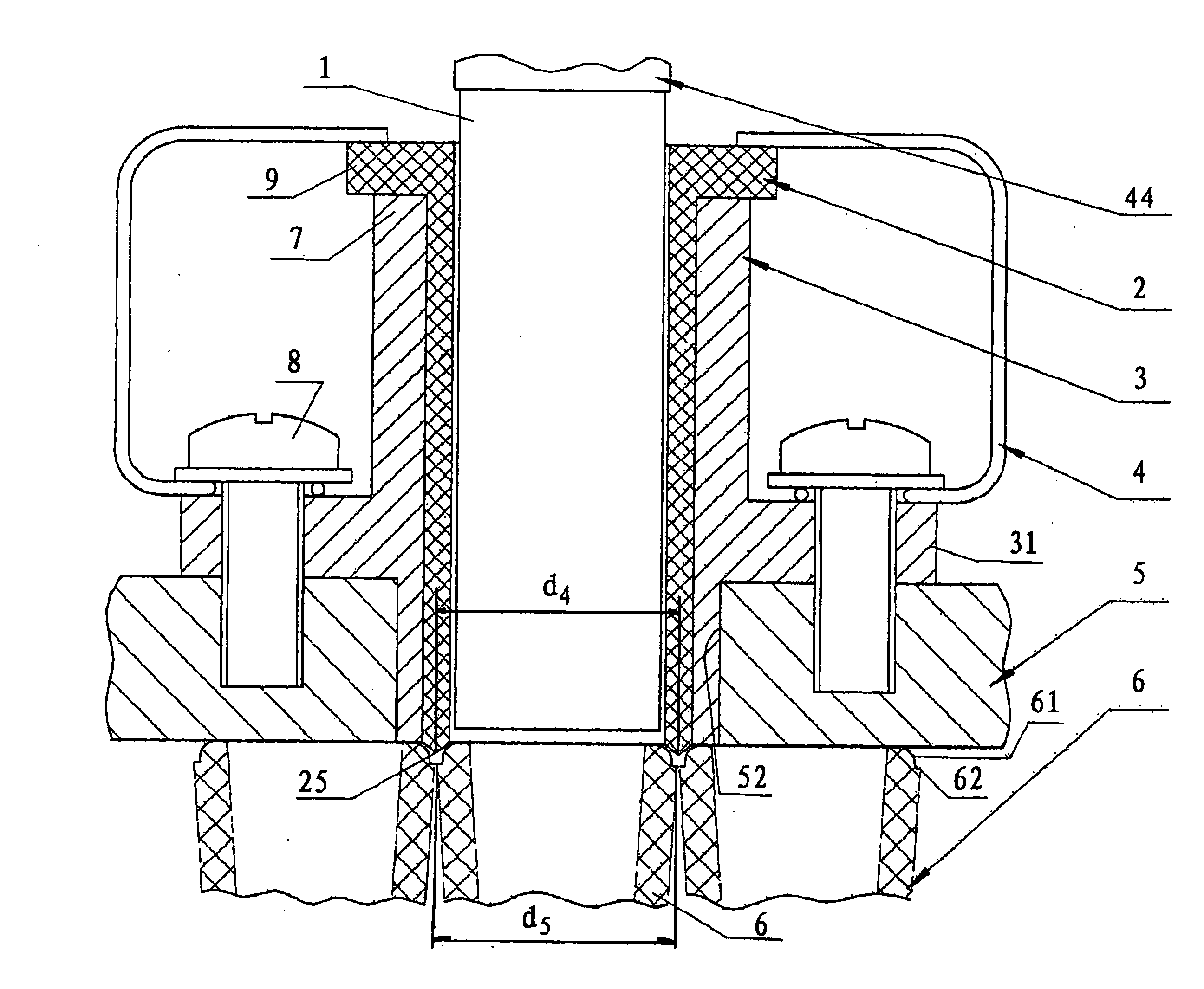
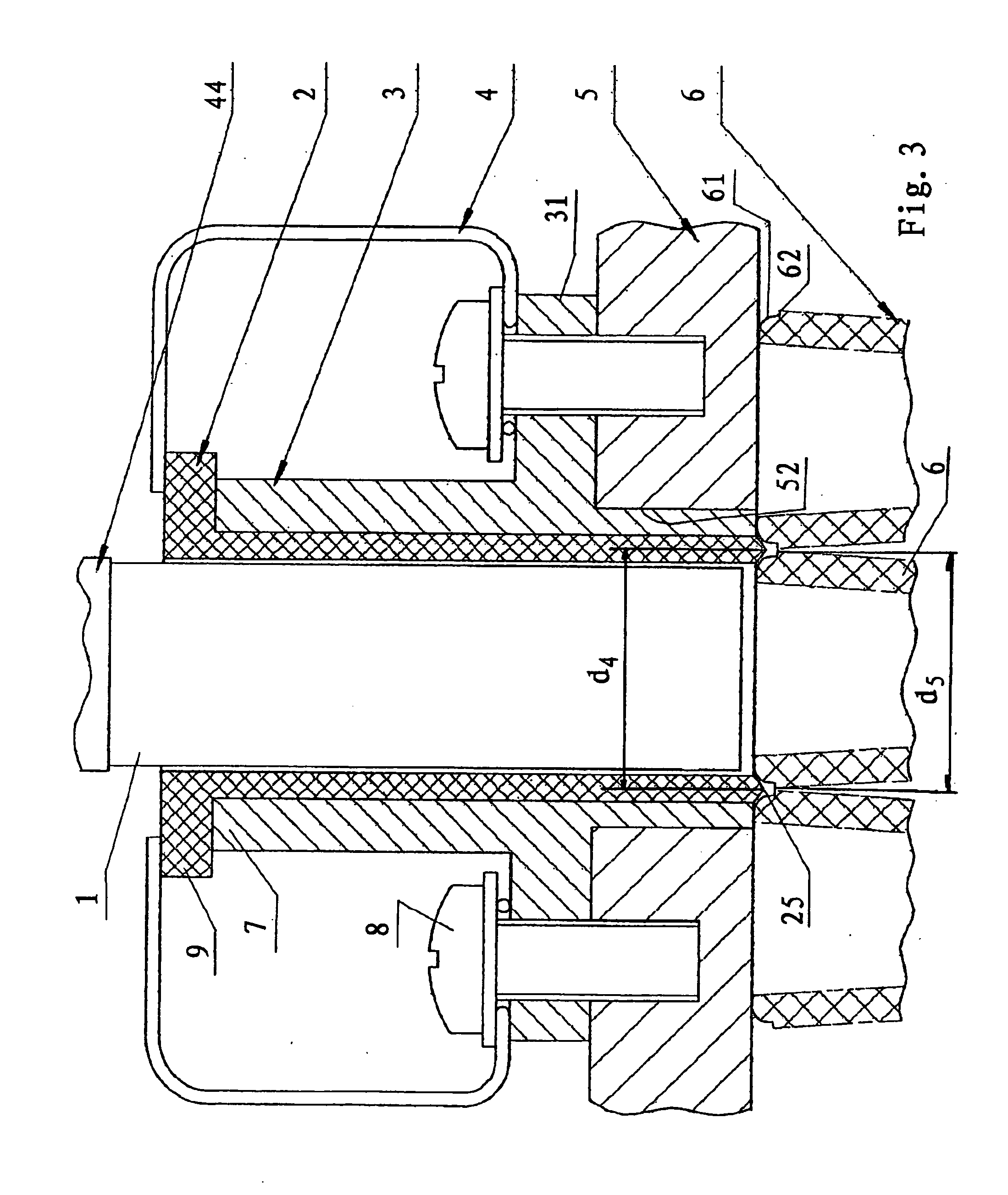
[0073] As shown in FIG. 3, a probe assembly used for a testing instrument determining optical signal in a test cell comprises: a top plate 5, constituting a part of the single photon counting device and the cover plate of it, formed with a through-hole 52; a cylindrical optical pickup 1, connecting with a photoelectric (photovoltaic) converter for picking up the optical signal of the sample in the test cell 5 and sending the picked signal to the photoelectric converter converting the picked optical signal to a electrical signal. In this embodiment, said optical pickup is a fiber optical tube, and said photoelectric converter is a photomultiplier assembly 24....


PUM

PropertyMeasurementUnit
friction coefficientaaaaaaaaaa
forceaaaaaaaaaa

Abstract

A probe assembly used in testing instrument for determining optical signal within a test cell, comprising a top plate (5;205) with a through-hole (52;250) therein; a cylindrical light hood (2;202) having a central channel (21;221); the lower end of the optical pickup (1) is inserted into said channel (21;221) and surrounded by said light hood, and said light hood can slide down and up within a small distance isolating said one test cell of the sample being detected from its adjacent cells and surroundings when the lower end of said light hood is in said protruding position, so that the light interference from the adjacent test cells and surroundings with (to) the determination of the sampling being detected can be avoided. Also, the present invention further relates to the light hood included in the probe assembly and the instruments including the probe assembly.

Description

TECHNICAL FIELD [0001] The present invention relates to a testing device, more particularly, to a probe assembly used in medical testing devices for determining optical signal in a test cell, a medical testing device and a micro-cellular-plate single photon counting device for determining optical signal in a test cell. BACKGROUND ART [0002] Recently, there are various kinds of known testing instruments for determining optical signal. Its principle is that the optical signal picked up or determined by a photo electric converter (transducer) is converted into voltage or current signal and then these voltage and current signal is amplified. With the quantum physics developing, a novel high-sensitivity photoelectric testing device so called a single-photon counting device has been manufactured and widely used in aviation, space-flight, military affairs, medical treatment, security, scientific research, environmental protection, agriculture, and industry etc. An example of applying a sin...

Claims


Application Information

Patent Timeline
Patent Type & Authority Applications(United States)
IPC IPC(8): G01N21/00G01J1/00G01N21/01G01N21/03G01N21/25G06M1/272
CPCG01J1/0214G01N21/0303
Inventor LIU, ENCONGYU, JINSHENGYANG, XIAOLINWU, XIAODONG
Owner BEIJING YUANDE BIO MEDICAL ENG
Why Eureka
Try Eureka