
Base station device and transmission method

Inactive Publication Date: 2006-09-14
PANASONIC CORP
View PDF3 Cites 95 Cited by
  • Summary
  • Abstract
  • Description
  • Claims
  • Application Information

AI Technical Summary

Benefits of technology

[0025] It is therefore an object of the present invention to provide a base station apparatus and transmission method for controlling the amount of transmission packet data requested for retransmission and stored in a buffer, thereby improving throughput and preventing disruption of communication and channel disconnections.

Problems solved by technology

Further, an AMD-PDU may be discarded by transmission error between the base station apparatus and mobile terminal.
However, when many AMD-PDUs are stored in the buffer in the MAC-hs processing section, the retransmitted AMD-PDU needs to wait long in the buffer, and does not immediately arrive at the RLC processing section of the mobile terminal.
Therefore, the RLC processing section of the radio network control apparatus repeats retransmission of the same AMD-PDU, and there arises a problem of decrease in throughput.
Then, when the number of retransmissions reaches a predetermined threshold, the RLC processing section of the mobile terminal discards all the stored data, while the RLC processing section of the radio network control apparatus also discards all the stored data, and this gives another problem that the communication is disrupted.
Further, when the number of times the RESET message is transmitted from the RLC processing section of the radio network control apparatus reaches a predetermined threshold due to an increased number of retransmissions, the RRC processing section starts up the process of disconnecting the radio channel used by the mobile terminal in response to a report from the RLC processing section, the radio channel used by the mobile terminal is thereby disconnected, and another problem further occurs that the mobile terminal cannot receive the service being used by the terminal.

Method used


Image

  • Base station device and transmission method
  • Base station device and transmission method
  • Base station device and transmission method

Examples


embodiment 1

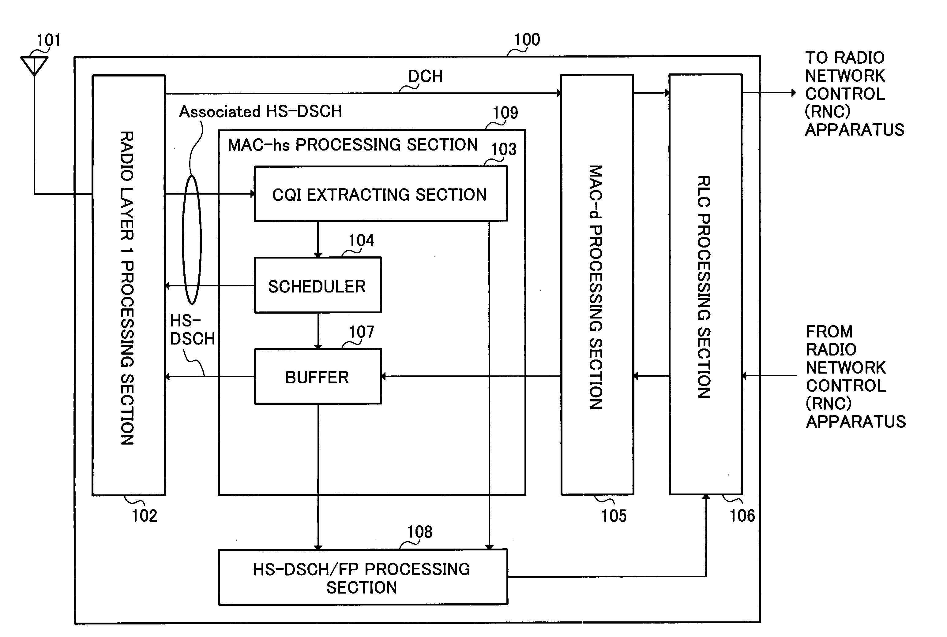
[0041] A configuration of base station apparatus 100 according to Embodiment 1 of the invention will be first described below with reference to FIG. 4. FIG. 4 is a block diagram illustrating the configuration of base station apparatus 100 according to Embodiment 1 of the invention.

[0042] MAC-hs processing section 109 is comprised of CQI extracting section 103, scheduler 104 and buffer 107.

[0043] Radio layer 1 processing section 102 performs radio signal processing on a received signal received in antenna 101 to output to CQI extracting section 103 and MAC-d (Medium Access Control used for dedicated) processing section 105. Radio layer 1 processing section 102 further performs radio signal processing on scheduling information input from scheduler 104 to transmit from antenna 101, while performing radio processing on high-speed packet communication data input from buffer 107 to transmit from antenna 101.

[0044] CQI extracting section 103 extracts a CQI that is reception quality info...

embodiment 2

[0083]FIG. 11 is a block diagram illustrating a configuration of HS-DSCH / FP processing section 108 in a base station apparatus according to Embodiment 2 of the invention. In addition, configurations of the base station apparatus and communication terminal apparatus are the same as in FIGS. 4 and 5 except threshold information input to HS-DSCH / FP processing section 108, and descriptions thereof are omitted.

[0084] CQI referring section 802 stores in the reference table the same transmission data rate information (reception quality information) associating the CQI with the transmission data rate as that in the communication terminal apparatus. CQI referring section 801 refers to the reference table using the CQI input from CQI extracting section 103, and is thereby capable of detecting the transmission data rate (TFRI). Then, CQI referring section 801 outputs detected transmission data rate information to queuing delay calculating section 802.

[0085] Queuing delay calculating section ...

embodiment 3

[0088]FIG. 12 is a block diagram illustrating a configuration of base station apparatus 900 according to Embodiment 3 of the invention. As shown in FIG. 12, base station apparatus 900 according to Embodiment 3 has separating section 901, and retransmission packet buffer 902 and new packet buffer 903 as a substitute for buffer 107 in base station apparatus 100 according to Embodiment 1 as shown in FIG. 4. In addition, in FIG. 12, the same structural elements as in FIG. 4 are assigned same reference numerals to omit descriptions thereof. A configuration of a communication terminal apparatus is the same as that in FIG. 5, and descriptions thereof are omitted.

[0089] Scheduler 104 holds a reference table storing modulation scheme information that associates a modulation scheme such as 16QAM with CQI, and another reference table storing coding rate information that associates a coding rate with CQI. Each of the base station and communication terminal apparatuses has the same reference ta...


PUM


Abstract

RLC processing section 106 supplies packet data requested for retransmission from a mobile terminal and new packet data not requested for retransmission to buffer 107 corresponding to data amounts controlled in HS-DSCH / FP processing section 108. Buffer 107 temporarily stores the packet data requested for retransmission and the new packet data not requested for retransmission to output at predetermined timing. HS-DSCH / FP processing section 108 detects a receivable data amount of the mobile terminal using CQI, and controls RLC processing section 106 so that the amount of data stored of packet data in buffer 107 does not exceed the receivable data amount of the mobile terminal. It is thereby possible to decrease the number of retransmissions to improve the throughput, and prevent suspension of the communication and disconnection of the channel.

Description

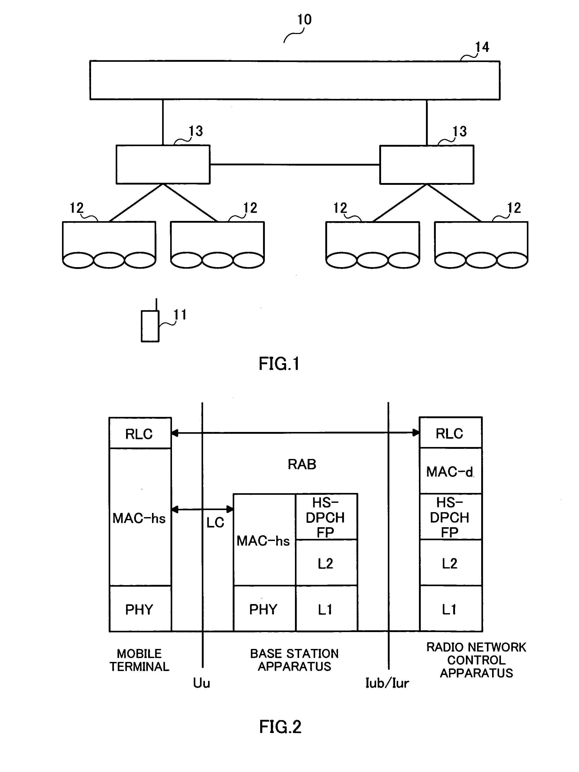
TECHNICAL FIELD [0001] The present invention relates to a base station apparatus and a transmission method. More particularly, the present invention relates to a base station apparatus and transmission method using an automatic repeat request system to recover a loss of a packet on a radio channel by retransmission of the packet. BACKGROUND ART [0002] As shown in FIG.1, mobile communication system 10 is comprised of mobile terminals 11, base station apparatuses 12, radio network control apparatuses 13 that control a plurality of base station apparatuses 12, and core network 14 that performs position management, call connection control and the like for the mobile terminals 11. [0003] HSDPA (High Speed Downlink Packet Access) techniques being standardized in 3GPP (3rd Generation Partnership Project) are applied to wireless transmission between mobile terminals 11 and base station apparatuses 12. [0004] HSDPA is new techniques whose standardization has proceeded in 3GPP, and achieves h...

Claims


Application Information

Patent Timeline
IPC IPC(8): H04Q7/00H04L1/16H04B7/26H04L1/18H04W28/00H04W28/04H04W28/06H04W28/14
CPCH04L1/0026H04L1/1874
Inventor FUKUI, AKITOIIDA, KENICHIROISHIMORI, TAKAYUKI
Owner PANASONIC CORP
Learn More