Substrate mounting table, substrate processing apparatus and substrate processing method

a substrate and mounting table technology, applied in the direction of coatings, chemical vapor deposition coatings, electric discharge tubes, etc., can solve the problems of poor temperature controllability, difficult to provide a desired temperature difference, and occur heat transfer therein, so as to achieve enhanced temperature controllability of the substrate mounting table

Active Publication Date: 2006-09-21
TOKYO ELECTRON LTD
View PDF5 Cites 47 Cited by
  • Summary
  • Abstract
  • Description
  • Claims
  • Application Information

AI Technical Summary

Benefits of technology

[0021] In accordance with the present invention, the temperature controllability by a substrate mounting table can be enhanced, so that a pro...

Problems solved by technology

Thus, even though two coolant passageways are provided to cause the temperature difference in the substrate mounting table as in the above-mentioned conventional method, there may occur heat transfer therein.
Accordingly, temperature controllability thereof is poor, and it is difficult to provide a desired temperature difference.
In other words, even if two coolant passageways are provided, the boundary between the ...

Method used


Image

  • Substrate mounting table, substrate processing apparatus and substrate processing method
  • Substrate mounting table, substrate processing apparatus and substrate processing method
  • Substrate mounting table, substrate processing apparatus and substrate processing method

Examples


first embodiment

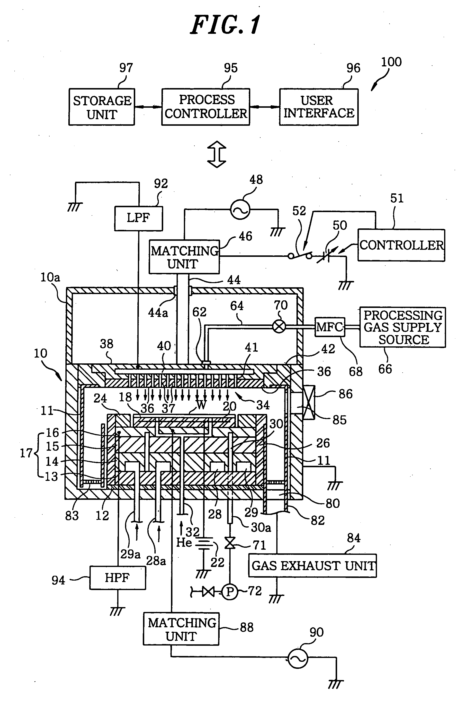
[0032]FIG. 1 illustrates a schematic cross sectional view of a plasma etching apparatus 100 as a substrate processing apparatus in accordance with the present invention.

[0033] The plasma etching apparatus 100 is configured as a capacitively coupled parallel plate type plasma etching apparatus, and has a cylindrical chamber (processing chamber) 10 made of aluminum, a surface of which is anodically oxidized. The chamber 10 is frame grounded.

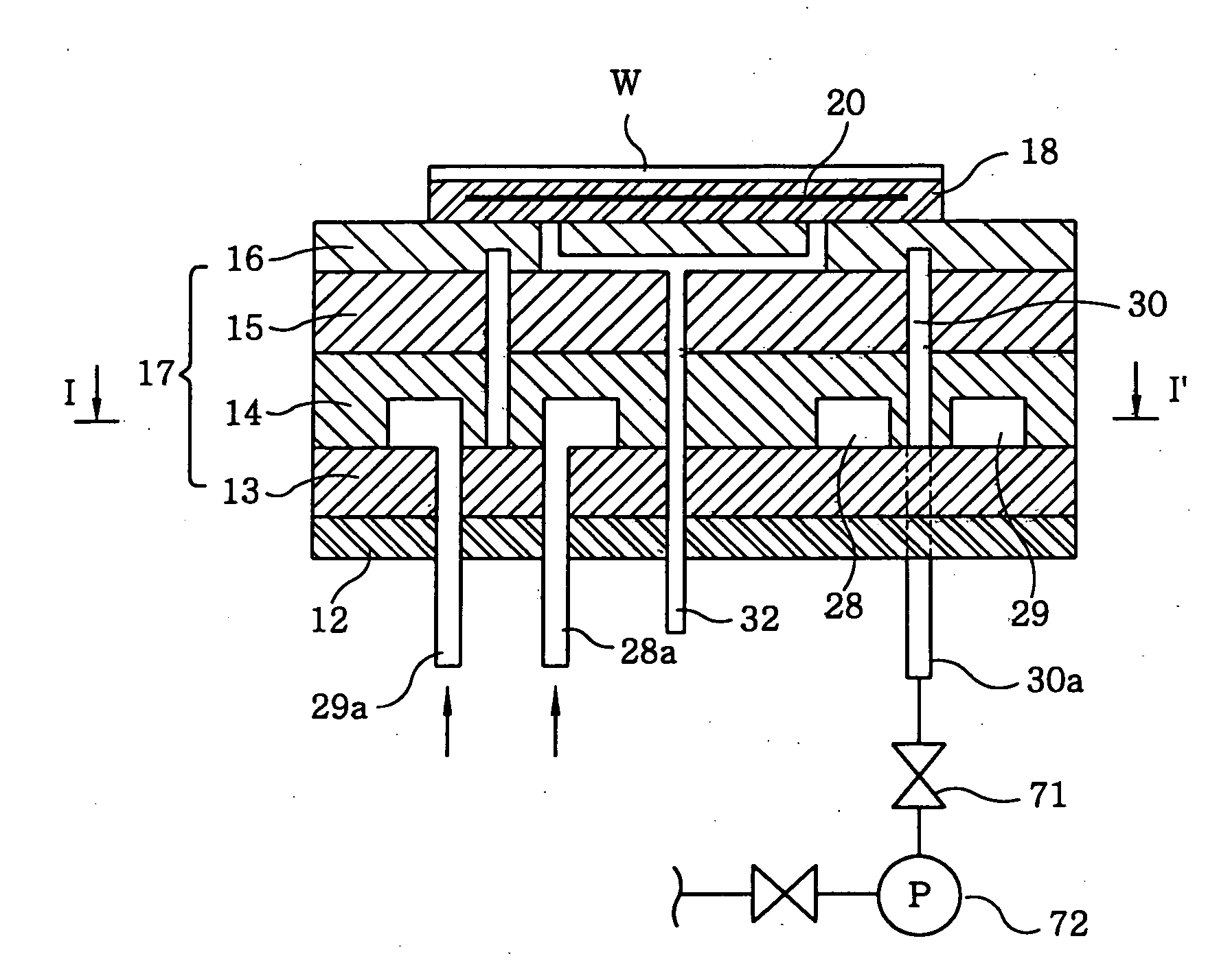
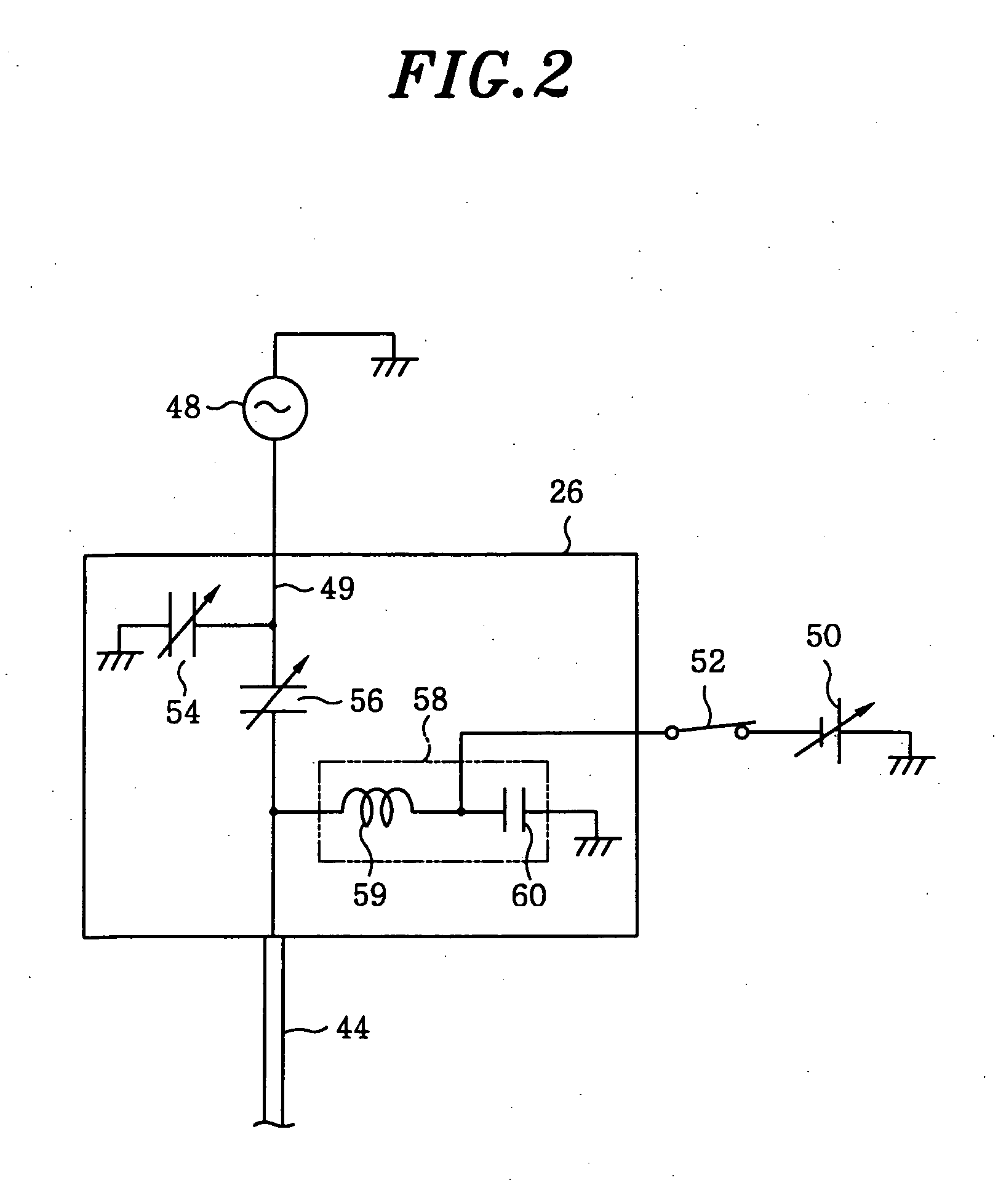
[0034] At a lower portion in the chamber, a first susceptor plate 13, a second susceptor plate 14, and a third susceptor plate 15 are sequentially stacked from the bottom on an insulation plate 12 made of ceramic or the like, and a fourth susceptor plate 16 is layered on the third susceptor plate 15. The first to the fourth susceptor plate 13 to 16 have a circular shape and are made of, e.g., aluminum. The first to fourth susceptor plates 13, 14, 15, and 16 are integrally attached to each other to form a substrate mounting table 17. A semiconducto...

second embodiment

[0065] In the substrate mounting table 17 of the second embodiment, by converting the state in the gap 30 from a vacuum state to a heat transfer medium-filled state and vice versa, the temperatures of the central area and the peripheral area of the substrate mounting table 17 can be controlled precisely and in a high degree of freedom depending on an intended purpose. Accordingly, in a case where the etching process for the wafer W is divided into a plurality of steps and the respective steps are conducted at different temperatures, the thermal conductivity of the gap 30 is changed in accordance with the processing conditions in each step, so that the temperature distribution of the substrate mounting table 17 can be rapidly controlled, thus carrying out the processing under optimum temperature conditions.

[0066]FIG. 6 is a flowchart of an exemplary temperature control sequence wherein etching processes are performed in two stages by using the plasma etching apparatus in accordance w...

third embodiment

[0073] In the third embodiment, two annular gaps 101 and 102 are arranged to extend upwards from a lower portion of the substrate mounting table 150 in a cylindrical shape. The upper portions of the gaps 101 and 102 are transversely enlarged to form enlarged parts 101b and 102b, respectively.

[0074] As shown in FIG. 7, the substrate mounting table 150 has a stacked structure wherein a first susceptor plate 151, a second susceptor plate 152, a third susceptor plate 153, and a fourth susceptor plate 154 are stacked sequentially from the bottom. An annular first chamber 131, an annular second chamber 132 and an annular third coolant passageway 133 are provided in the substrate mounting table 150 in that order from the inside to the outside. The gap 101 is provided between the first and second coolant passageways 131 and 132, and the gap 102 is provided between the second and third coolant passageways 132 and 133. Further, heaters 103 and 104 serving as a temperature control unit are ins...


PUM

PropertyMeasurementUnit
Temperatureaaaaaaaaaa
Pressureaaaaaaaaaa
Shapeaaaaaaaaaa

Abstract

A substrate mounting table includes a plurality of passageways independently provided therein, a temperature control medium flowing through the passageways, and a gap formed between at least two of the passageways. In a substrate processing method for processing a substrate mounted on the substrate mounting table in a substrate processing apparatus while controlling a temperature thereof, a process is performed on the substrate while controlling the temperature of the substrate by flowing the temperature control medium through each of the passageways. The passageways are respectively provided in a central area of the substrate mounting table and a peripheral area located outside the central area, and the central area and the peripheral area are thermally isolated from each other by evacuating the gap so as to set the gap to a vacuum state.

Description

FIELD OF THE INVENTION [0001] The present invention relates to a substrate mounting table for mounting thereon a substrate to be processed such as a semiconductor wafer while various processes are performed on the substrate, a substrate processing apparatus having the substrate mounting table, and a substrate processing method of processing the substrate by using the substrate processing apparatus. BACKGROUND OF THE INVENTION [0002] Recently, in manufacturing semiconductor devices, semiconductor wafers (hereinafter, referred to as “wafers”) as substrates to be processed undergo an intended process one by one while being mounted on a wafer mounting table. In this case, it is important to ensure reproducibility when a plurality of wafers is processed, and to uniformly process the surface of a single wafer sheet. For example, when a plasma etching process is performed on a wafer, it is preferable that the substrate mounting table have a temperature control function for controlling the ...

Claims


Application Information

Patent Timeline
IPC IPC(8): C23F1/00C03C25/68
CPCH01J37/32724H01L21/67109H01L21/67248H01L21/68785
Inventor OOHASHI, KAORUHAYAMI, TOSHIHIRO
Owner TOKYO ELECTRON LTD
Why Eureka
Try Eureka