Power tool torque overload clutch

Inactive Publication Date: 2006-09-21
BLACK & DECKER INC
View PDF17 Cites 14 Cited by
  • Summary
  • Abstract
  • Description
  • Claims
  • Application Information

AI Technical Summary

Benefits of technology

[0020] The present invention also provides a method of manufacturing a clutch comprising a first component for transmitting a drive force from a motor to an output spindle, and a second component for interrupting the drive force when a predetermined torque force is applied to the output spindle, the method comprising forming a gear-cog having a cavity for accommodating the first and second components, disposing the first and second components into the cavity of the gear-cog, and inserting a fastening means to hold the components in the cavity. Preferably, the fastening means is a threaded thrustplate having a threaded portion arranged

Problems solved by technology

However, if the drill bit becomes blocked or jammed in the work-piece then a torque force exceeding the predetermined torque is applied to the clutch, causing the clutch to operate or ratchet and interrupt power from the motor to the ham

Method used


Image

  • Power tool torque overload clutch
  • Power tool torque overload clutch
  • Power tool torque overload clutch

Examples


first embodiment

[0038] Furthermore, the threaded thrustplate arrangement provides a safer means to manufacture a clutch according to this embodiment because the springs are compressed as the thrustplate is threaded into the gear. By comparison, the first embodiment requires the springs to be under compression as the circ-clip is inserted in to the groove. If the circ-clip does not locate properly, the springs might force the circ-clip out of engagement with the groove causing components to spring-out of the gear at relatively high velocities. This may result in damage to machinery or injury to an operative.

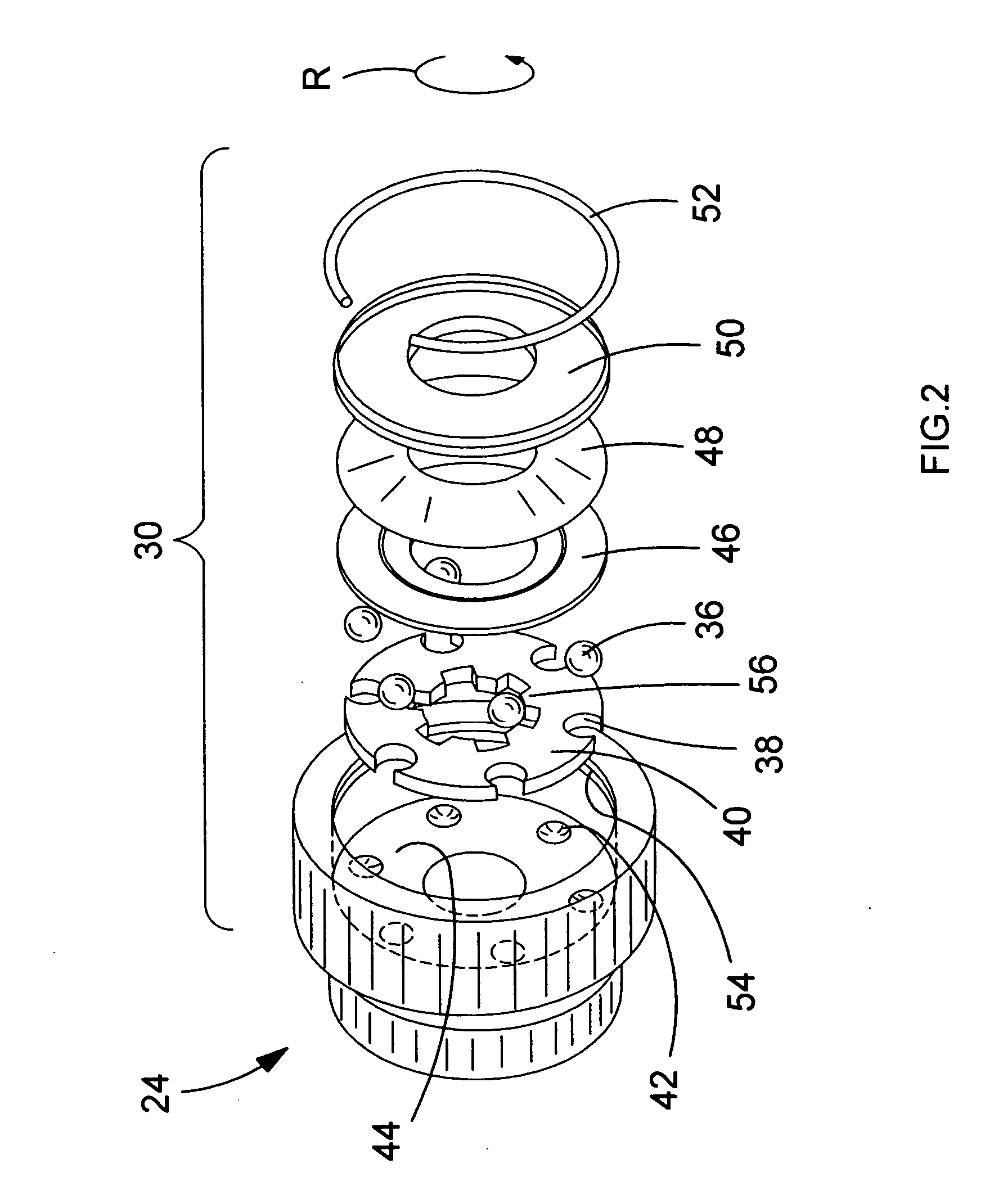
[0039] The outer surface of the threaded thrustplate can be arranged so that it is flush with the gear mechanism 24 when threaded into position against the step 70. Thus, a compact clutch and gear mechanism can be achieved.

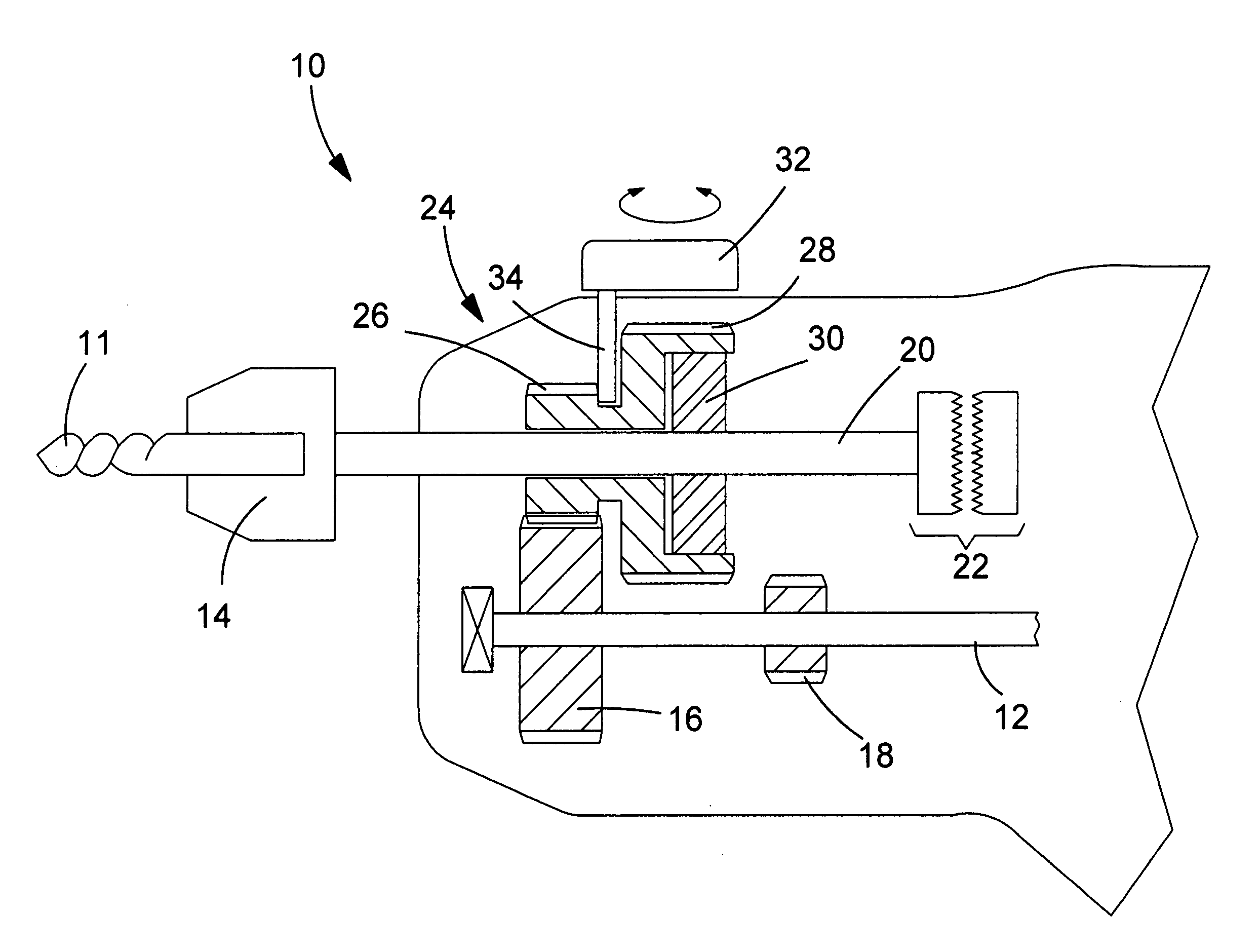
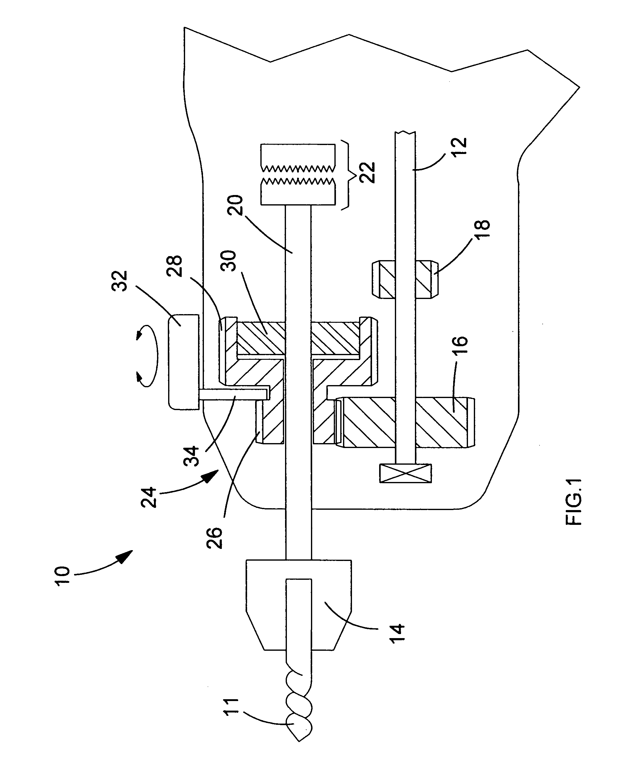
[0040] By disposing the torque overload clutch on the output spindle gear 24, it is possible for the clutch to interrupt the drive to the output spindle at a consistent predet...

second embodiment

[0041] The gear mechanism 24 can be formed from a single piece of material. The cavity and raceway or indentation into which the clutch's balls locate can be formed by a sintering method. In the second embodiment the step might also be formed by a sintering method. This provides a means for mass-producing a clutch mechanism with relatively high tolerances thus reducing any variance of overload force needed before the clutch ratchets. In other words, the standard deviation of forces required to overload clutches in a manufacturing batch can be reduced because the manufacturing tolerances are reduced using these techniques.

[0042] Furthermore, by utilising a single-piece gear-cog, a clutch of the prior art is simplified and improved upon. For instance, the clutch described in DE2522446 has various drive components press fitted onto the central spline or onto a gear. Thus, the torque range in which the clutch can operate is limited; if the torque exceeds a given amount, then the compone...


PUM

PropertyMeasurementUnit
Forceaaaaaaaaaa
Torqueaaaaaaaaaa

Abstract

A torque overload clutch for an electrical power tool, such as a percussion hammer drill, is provided. The clutch is accommodated in a cavity in a gear cog. Spring washers are used to urge ball bearings into indentations formed in the base of the cavity. The ball bearings are accommodated in cavities formed in a drive plate which engages with the spindle drive of the power tool. The spring washers are held in position by a circlip or a threaded plate. The threaded plate arrangement provides means for compressing the spring washers with a consistent force across a manufactured batch. A method of manufacturing the clutch is also disclosed.

Description

FIELD OF THE INVENTION [0001] The present invention relates to a torque overload clutch which is suited for use in power tools, especially electrically powered hammer drills. The present invention also relates to a power tool comprising such a clutch mechanism. BACKGROUND OF THE INVENTION [0002] Embodiments of the invention are described below with reference to hammer drills. However, the inventive concept is not limited to such devices and a clutch embodying the invention can equally find use in other power tools such as circular saws or grinders, for instance. [0003] During normal operation of a hammer drill a drill bit is caused to rotate whilst, at the same time, the drill bit receives repeated impacts. Such drills are often used for working masonry, or the like. The impact mechanism can be of a pneumatic or percussion type, known in the art. Furthermore, the hammer drill can be arranged to operate in hammer-drill mode, where the drill bit receives impacts as it rotates, and dri...

Claims


Application Information

Patent Timeline
IPC IPC(8): B25B21/02
CPCB25D16/003B25D2250/165B25D2250/321
Inventor ARMSTRONG, JONATHAN
Owner BLACK & DECKER INC
Why Eureka
Try Eureka