
Atmospheric transfer chamber, processed object transfer method, program for performing the transfer method, and storage medium storing the program

Inactive Publication Date: 2006-09-21
TOKYO ELECTRON LTD
View PDF6 Cites 127 Cited by
  • Summary
  • Abstract
  • Description
  • Claims
  • Application Information

AI Technical Summary

Benefits of technology

[0012] It is, therefore, an object of the present invention to provide an atmospheric transfer chamber, a processed object transfer method, a program for performing the transfer method, and a storage medium storing the program capable of preventing quality of a semiconductor device fabricated from a target object from deteriorating while improving an operation rate of an object processing apparatus.
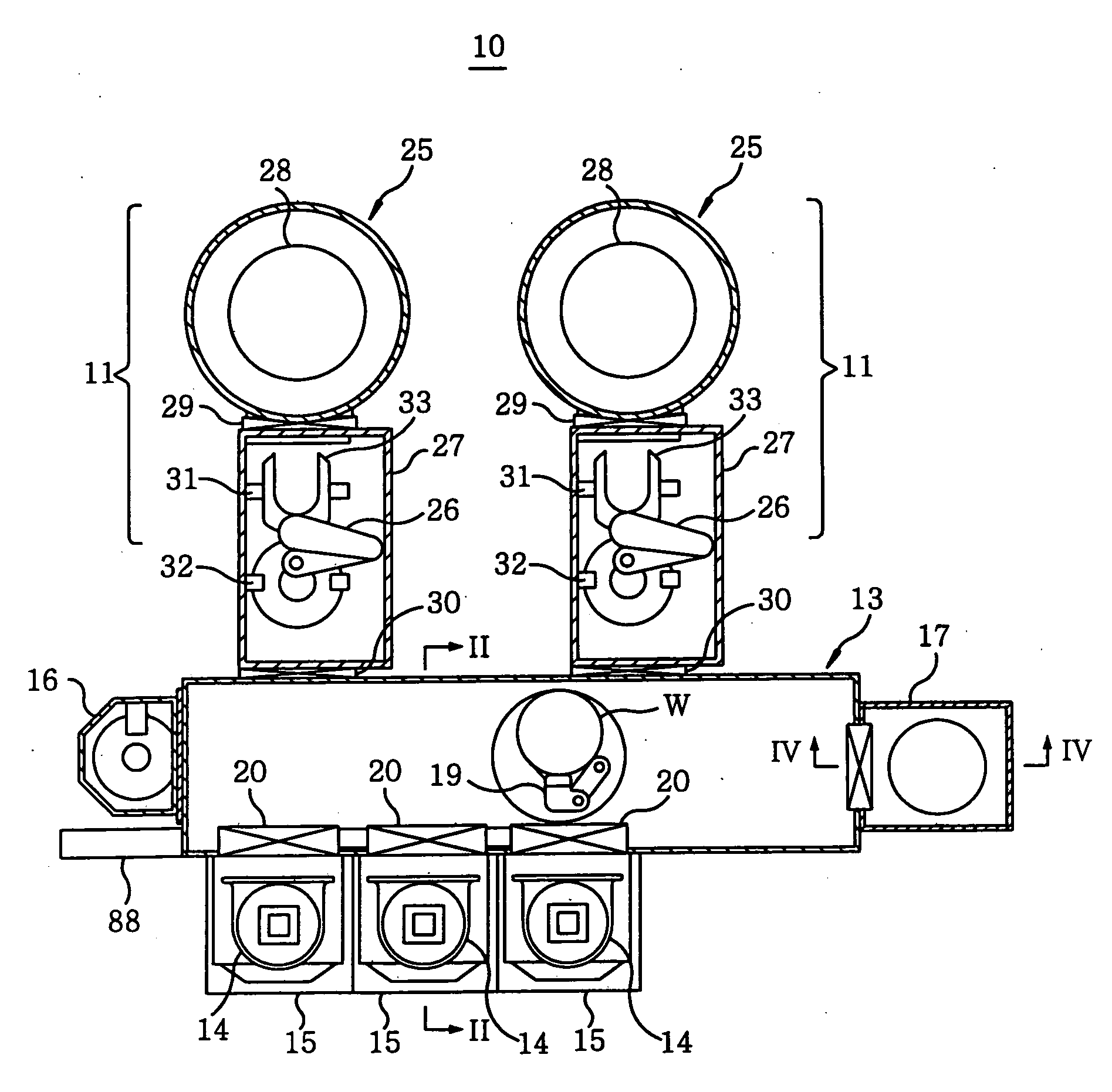
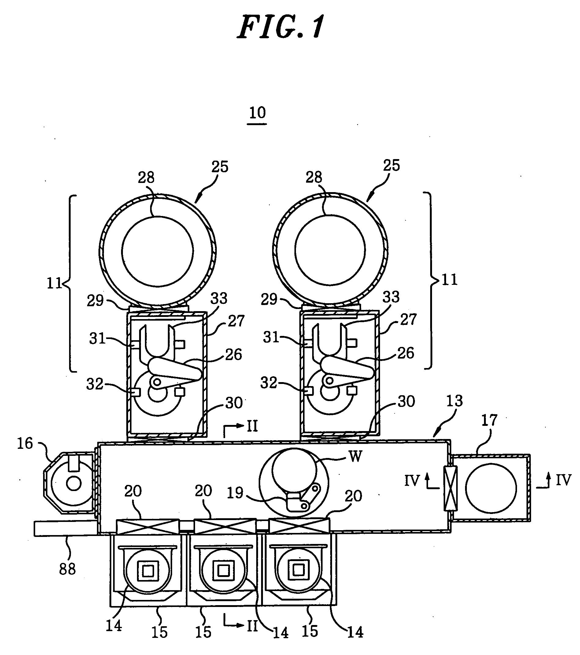
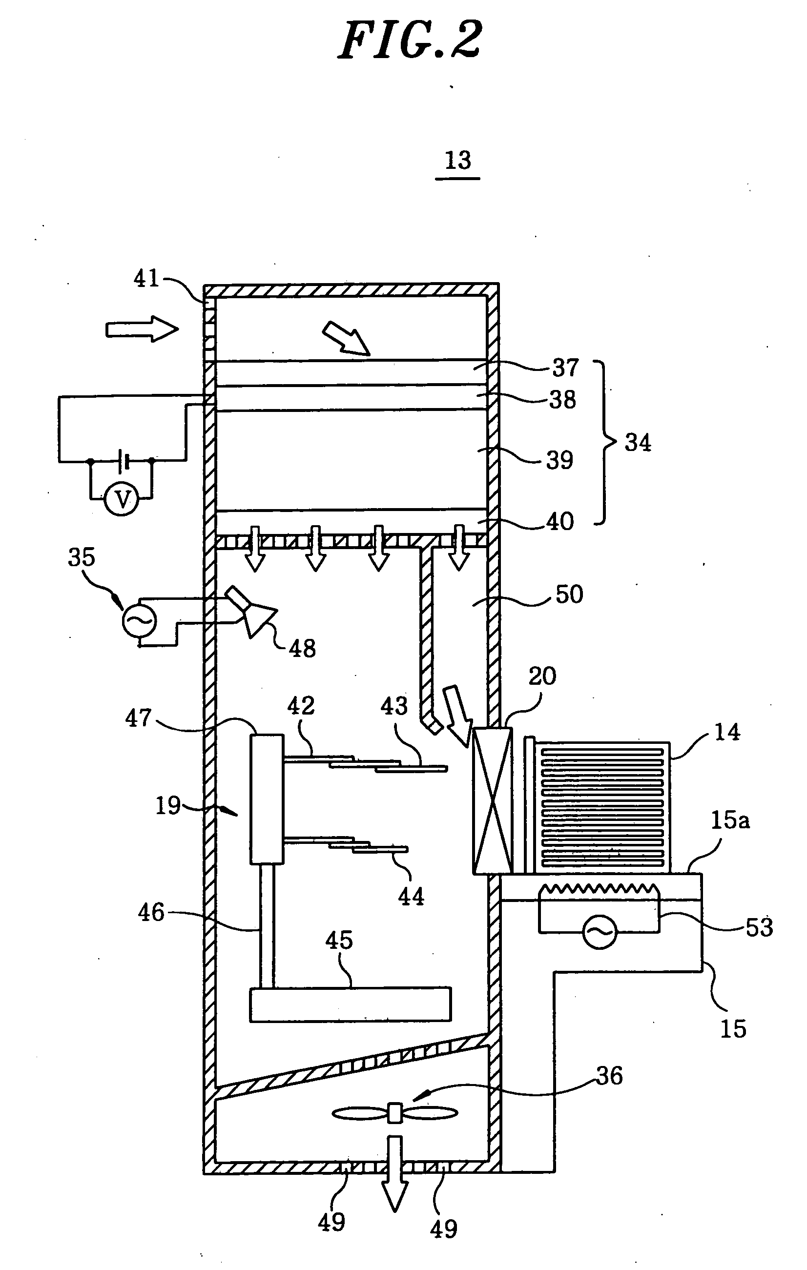
[0013] To achieve the object, in accordance with a first aspect of the present invention, there is provided an atmospheric transfer chamber, connected to an object processing chamber for processing a target object by using a plasma of a halogen-based gas, for transferring the target object therein, the atmospheric transfer chamber including a dehumidifying unit for dehumidifying air in the atmospheric transfer chamber. Since the inside of the atmospheric transfer chamber for transferring the target object processed by using a plasma of a halogen-based gas is dehumidified, reaction products of a halogen-based gas attached to the target object do not react with water, a halogen-based acid gas is prevented from being produced from the target object. As a result, generation of oxide is suppressed in the atmospheric transfer chamber, and it is possible to prevent the quality of a semiconductor device fabricated from the target object from being deteriorated and improve an operation rate of the object processing apparatus.
[0014] In the atmospheric transfer chamber, the dehumidifying unit may include a desiccant filter. Accordingly, the inside of the atmospheric transfer chamber can be efficiently dehumidified. Further, the desiccant filter can be recovered during a dehumidifying process, which, in turn, further improves an operation rate of the object processing apparatus.

Problems solved by technology

However, in this substrate processing apparatus, in order that the wafer etched in the etching chamber is vacuum transferred to the corrosion passivation chamber, the corrosion passivation chamber needs to be arranged in a vacuum state, which inevitably complicates the configuration of the substrate processing apparatus.
The oxide layer is peeled from the inner wall and the surface due to the vibration generated while the wafer is transferred by the wafer transfer arm and turns into particles to be attached to the surface of the wafer, which in turn deteriorates quality of the semiconductor device fabricated from the wafer.

Method used


Image

  • Atmospheric transfer chamber, processed object transfer method, program for performing the transfer method, and storage medium storing the program
  • Atmospheric transfer chamber, processed object transfer method, program for performing the transfer method, and storage medium storing the program
  • Atmospheric transfer chamber, processed object transfer method, program for performing the transfer method, and storage medium storing the program

Examples


third embodiment

[0118] Hereinafter, there will be described an atmospheric transfer chamber in accordance with the present invention.

[0119] The third preferred embodiment has a substantially same configuration and effects as those of the first preferred embodiment except an FFU structure. Specifically, the third embodiment is different from the first embodiment in that FFU does not include a dehumidifying unit and the dehumidifying unit is disposed outside the loader module. Thus, description of repeated configuration and effects is omitted and only different configuration and effects will be described later.

[0120]FIG. 7 depicts a cross sectional view showing a schematic configuration of a loader module serving as an atmospheric transfer chamber in accordance with the third preferred embodiment.

[0121] As shown in FIG. 7, a loader module 71 includes therein an FFU 72 disposed at an upper side a transfer arm unit 19; an ionizer 35; a duct fan 36 disposed at a lower side; and air inlet openings 41 d...

fifth embodiment

[0140] To solve this problem, in the fifth embodiment, the loader module 80 has an in-chamber heating unit 81 therein. The in-chamber heating unit 81 includes a plurality of halogen lamps, and each halogen lamp illuminates the inner wall of the loader module 80 and the surface of the transfer arm unit 19 (hereinafter, simply referred to as “the inner wall and the surface”). At this time, since illuminated inner wall and surface are heated by heat rays emitted from the halogen lamps, the acid generated in the loader module 80 is evaporated as soon as it gets in contact with the inner wall and the surface without being attached thereto. Thus, it is possible to prevent the inner wall and the surface from being corroded in the loader module 80.

[0141] Further, the heating unit 81 in the transfer chamber can be anything capable of heating the inner wall and the surface, for example, a ceramic heater or an infrared lamp, without being limited to the plurality of halogen lamps.

[0142] In th...


PUM

PropertyMeasurementUnit
Temperatureaaaaaaaaaa
Humidityaaaaaaaaaa

Abstract

An atmospheric transfer chamber, connected to an object processing chamber for processing a target object by using a plasma of a halogen-based gas, for transferring the target object therein, the atmospheric transfer chamber includes a dehumidifying unit for dehumidifying air in the atmospheric transfer chamber. The dehumidifying unit includes a desiccant filter, a cooling unit for cooling the air introduced into the atmospheric transfer chamber, and an air conditioner. The atmospheric transfer chamber is connected to a reaction product removal chamber for removing reaction products of a halogen-based gas attached to the target object, wherein halogen in reaction products attached to the target object is reduced.

Description

CROSS-REFERENCE TO RELATED APPLICATIONS [0001] This document claims priority to Japanese Patent Application Number 2005-78092, filed Mar. 17, 2005 and U.S. Provisional Application No. 60 / 666,703, filed Mar. 31, 2005, the entire content of which are hereby incorporated by reference. [0002] 1. Field of the Invention [0003] The present invention relates to an atmospheric transfer chamber, a processed object transfer method, a program for performing the transfer method, and a storage medium storing the program; and, more particularly, to an atmospheric transfer chamber for transferring an object that is processed by a plasma of a halogen-based gas. [0004] 2. Background of the Invention [0005] Typically, in a substrate (hereinafter, referred to as a “wafer”) that is a target object formed of silicon (Si) for a semiconductor device, a trench (groove) is formed therein by etching a polysilicon layer on the wafer in order to form a gate electrode and the like. The etching of the polysilicon...

Claims


Application Information

Patent Timeline
IPC IPC(8): C23F1/00H01L21/306B44C1/22
CPCC23F1/12H01L21/02071H01L21/67017H01L21/67109H01L21/67775H01L21/02
Inventor MORIYA, TSUYOSHIHIROOKA, TAKAAKISHIMIZU, AKITAKATANAKA, SATOSHI
Owner TOKYO ELECTRON LTD
Learn More