

Optical performance restoring equipment, restoring method
A technology of optical performance and recovery method, applied in the field of invention, can solve problems such as difficulty in long-term monitoring
- Summary
- Abstract
- Description
- Claims
- Application Information
AI Technical Summary
Problems solved by technology
Method used
Image

Examples
Embodiment 1
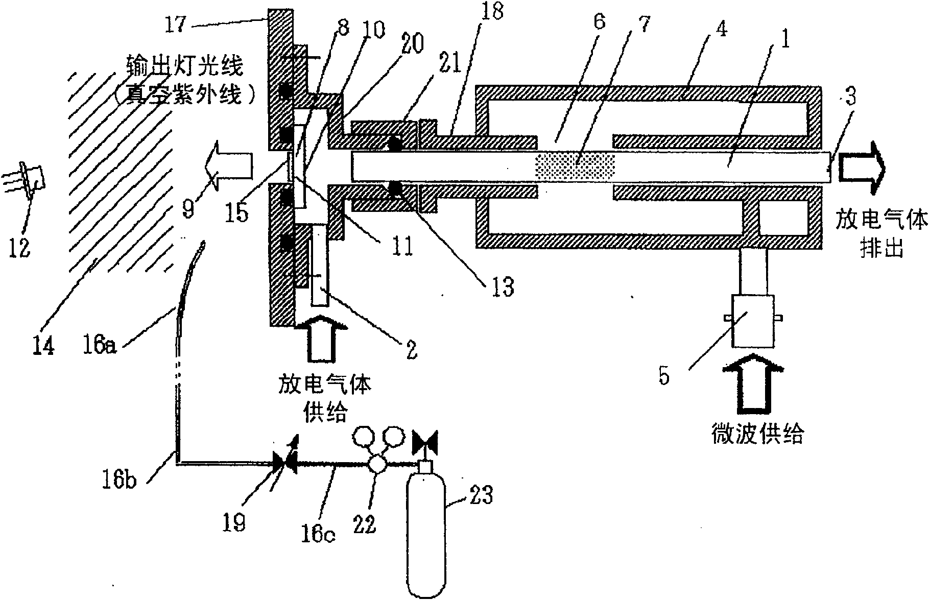
[0134] figure 1 is a schematic diagram showing the structure of a microwave-excited hydrogen ultraviolet lamp according to the first example of the first preferred embodiment of the present invention.
[0135] The holder (flange) 17 to which the light transmission window 8 is connected is disc-shaped and its center is aligned with the hole of the discharge tube 1, which includes an opening having a diameter larger than the inner diameter of the discharge tube. The window flange 17 includes an O-ring groove to create a seal over the entire opening of the light transmission window 8, and a hollow cover-like mounting bracket 20, for attaching its bolt holes, and for connection to the discharge vessel 1 for use with the window flange. 17 O-ring grooves to maintain vacuum.
[0136] The internal structure of the assembly frame 20 adopts two-stage concentric circles and limits the space for accommodating the light transmission window 8 and the space surrounded by the discharge tube...
Embodiment 2
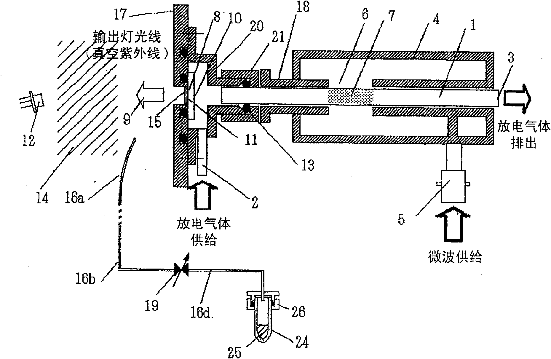
[0160] figure 2 is a schematic diagram showing a microwave-excited hydrogen ultraviolet lamp according to a second example of the first preferred embodiment of the present invention. Detailed descriptions of other structures and operating elements that are the same as those described in Embodiment 1 are omitted here. The specifications of the light transmission window 8 are the same as those described in Embodiment 1. In addition, a photodiode 12 is positioned as means for monitoring the light output of said lamp to receive the light output of light 9 emitted by the lamp.
[0161] Water vapor was supplied to the vacuum zone 14 and adjusted to a predetermined gas partial pressure by the method described below. A glass tube 24 (tube diameter Φ6 mm) filled with 1 mL of water 25 (pure water for distillation, ion exchange treatment and filtration) is connected to the tube 16d through the flange 17 . The construction of the flange 17 combined with an O-ring seals the glass tube ...
Embodiment 3
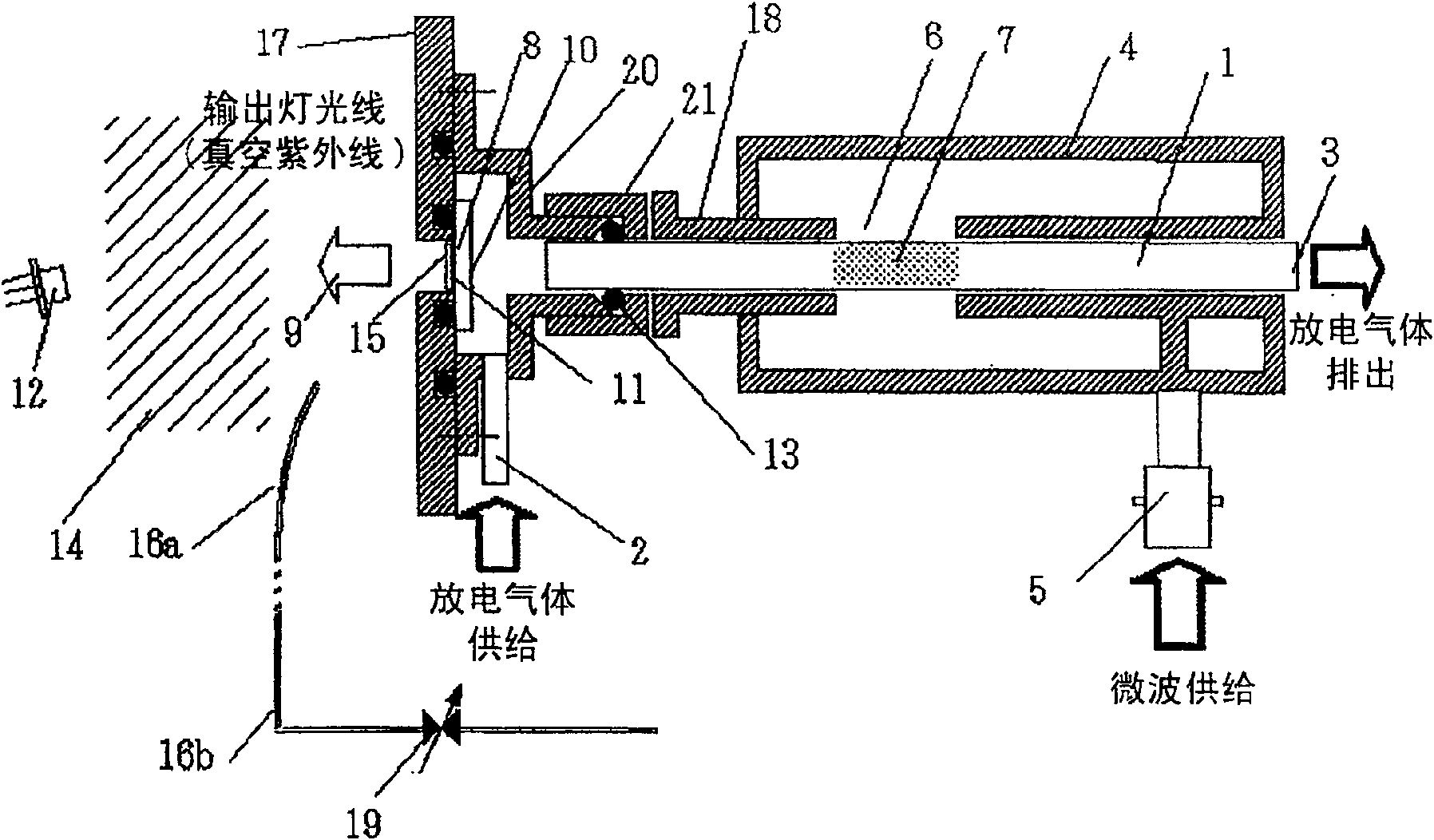
[0172] image 3 is a schematic diagram showing a microwave-excited hydrogen ultraviolet lamp according to a third example of the first preferred embodiment of the present invention. Detailed descriptions of other structures and operating elements that are the same as those described in Embodiment 1 are omitted here. The specifications of the light transmission window 8 are the same as those described in Embodiment 1. In addition, a photodiode 12 as means for monitoring the light output of said lamp is positioned to receive the light output of light 9 emitted by the lamp.
[0173] Atmospheric components are supplied to the vacuum zone 14 and adjusted to a prescribed gas partial pressure by the method specified below.
[0174]After the orifice is adjusted by the variable leak valve 19, the atmospheric component is fed to the vacuum zone 14 through a tube open to atmosphere allowing the atmospheric component to flow through tube 16b, and through a sealing mechanism (not shown) ...
PUM
| Property | Measurement | Unit |
|---|---|---|
| particle size | aaaaa | aaaaa |
| diameter | aaaaa | aaaaa |
| diameter | aaaaa | aaaaa |
Abstract
Description
Claims
Application Information