Discharge tube and surge absorbing device

a technology of surge absorption and discharge tube, which is applied in the direction of spark gap details, circuit arrangements, emergency protective arrangements for limiting excess voltage/current, etc., can solve the problems of shortening the lifetime of discharge tubes, triggering discharge films, and extending the life of discharge tubes

Inactive Publication Date: 2006-09-21
OKAYA ELECTRIC INDS
View PDF1 Cites 23 Cited by
  • Summary
  • Abstract
  • Description
  • Claims
  • Application Information

AI Technical Summary

Benefits of technology

[0030] In order to achieve the first object, inventors, after variously studying composite materials of a discharge gas encapsulated in an airtight envelope, found that Kr (krypton) that is large in the atomic weight and small in the thermal conductivity is very effective in improving the lifetime characteristics of a discharge tube, and thereby came to completion of the invention.

Problems solved by technology

However, since the lifetime characteristics of the existing discharge tube 60 is not necessarily at a satisfying level, a discharge tube having a further longer lifetime is expected.
The generation of the sputtering is a primary cause of shortening the lifetime of the discharge tube 60.
Furthermore, the existing triggering discharge film 78 constituted of a carbon base material of which primary raw material is graphite could not necessarily sufficiently inhibit the initial discharge from delaying.

Method used


Image

  • Discharge tube and surge absorbing device
  • Discharge tube and surge absorbing device
  • Discharge tube and surge absorbing device

Examples


Embodiment Construction

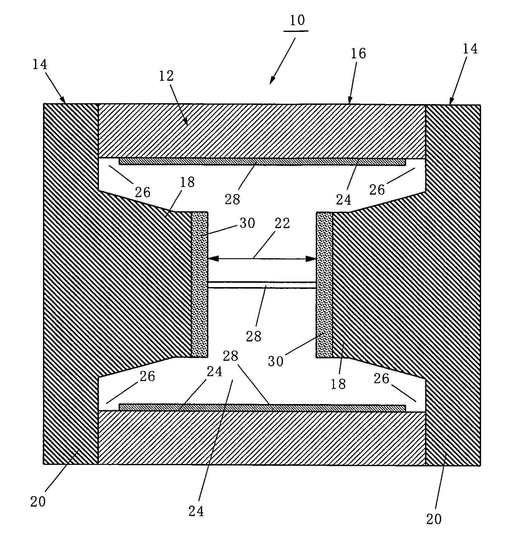
[0088]FIG. 1 shows a first discharge tube 10 according to the invention. The first discharge tube 10 corresponds to claims 1 through 4.

[0089] The first discharge tube 10 according to the invention, as shown in FIG. 1, is constituted by forming an airtight envelope 16 by hermetically clogging openings at both ends of a cylindrical case member 12 that is made of an insulating material such as ceramics, of which both ends are opened, with a pair of cap members 14, 14 that double as a discharge electrode.

[0090] The cap member 14 includes a planar discharge electrode portion 18 largely protruded toward a center of the airtight envelope 16 and a connection portion 20 that is in contact with an end surface of the case member 12. Between the discharge electrode portions 18, 18 of the both cap members 14, 14, a predetermined discharge gap 22 is formed.

[0091] Furthermore, on an inner wall surface 24 of the case member 12, a plurality of linear triggering discharge films 28 both ends of whi...


PUM


Abstract

A discharge tube 10 formed by forming an airtight envelope 16 by hermetically sealing openings at both ends of a case member 12 made of an insulating material opened at both ends with a pair of cap members 14, 14 that double a discharge electrode, forming a predetermined discharge gap 22 between discharge electrode portions 18, 18 of the cap members 14, 14, forming on an inner wall surface 24 of the case members 12 a plurality of linear triggering discharge films 28 of which both ends are disposed separated by a small discharge gap 26 opposite to the cap members 14, 14 that double a discharge electrode, forming on a surface of the discharge electrode portion 18 a film 30 containing an alkali iodide, and encapsulating a discharge gas containing Kr (krypton) in the airtight envelope 16.

Description

TECHNICAL FIELD [0001] The present invention relates to; a discharge tube that can be preferably used as a switching spark gap for supplying a turning-on or igniting constant voltage to a high-pressure discharge lamp such as a metal halide lamp for projectors and automobiles or an ignition plug of a gas cooker, or a gas arrestor (lighting conductor) for absorbing a surge voltage; and a surge absorber that absorbs a surge such as an indirect lighting stroke by making use of a discharge phenomenon in a discharge gap sealed in an air-tight envelope to inhibit an electronic instrument from being damaged, in particular, uses a creeping corona discharge as triggering means to aerial discharge. BACKGROUND ART [0002] So far, as a switching spark gap for supplying a turning-on or igniting constant voltage to a high-pressure discharge lamp such as a metal halide lamp for projectors and automobiles or an ignition plug of gas cookers, a discharge tube has been used. [0003] Furthermore, so far, ...

Claims


Application Information

Patent Timeline
Patent Type & Authority Applications(United States)
IPC IPC(8): H02H9/06H01J17/20H01J17/40H01T4/12
CPCH01J17/20H01J17/40H01T4/12H01T1/24H01J2201/30453
Inventor IMAI, KOICHIHORI, SATOSHIMATSUYAMA, YOICHIHANAMURA, YOSHIKAZU
Owner OKAYA ELECTRIC INDS
Why Eureka
Try Eureka