Microphone system for bone anchored bone conduction hearing aids

Inactive Publication Date: 2006-09-21
OTICON
View PDF9 Cites 24 Cited by
  • Summary
  • Abstract
  • Description
  • Claims
  • Application Information

AI Technical Summary

Benefits of technology

[0011] All of the above mentioned solutions may be built into different types of bone anchored bone conduction hearing aid systems. It may be a system where the vibrator of the hearing aid is positioned outside the skull and where there is a percutaneous abutment that goes through the skin and connects to a fixation in the skull bone. The advantage with such a system is that the hearing aid portion can easily be taken off if it for example needs to be repaired. The above mentioned solutions may also be applied in a bone anchored bone conduction hearing aid system where the vibrator is implanted under the skin and where there are no skin penetration since the signal and the energy to the vibrator is transmitted cordless by for example FM transmission and an inductive link. The vibrator may get power from an external battery via a cordless link or may be powered by an implanted battery. When the implanted battery needs to be charged this could be done via a cordless link transferring energy from an external power source. An a

Problems solved by technology

Bone anchored bone conduction hearing aids have significant problems with patients experiencing that the sound is mainly picked up from the rear since the device is usually placed behind the ear.
Directional microphones has been tried to overcome this problem but these have shown to have other limitations in performance.
Another problem with bone conduction hearing aids is that feedback problems may occur both due to sound radiating out from the skull and going back into the microphone, and due to vibrations that are transmitted from the vibrator to the microphone.
Feedback can also Arrangements that have been done to reduce such feedback problems have often had significant limitations in its performance and this limits the outpu

Method used


Image

  • Microphone system for bone anchored bone conduction hearing aids
  • Microphone system for bone anchored bone conduction hearing aids
  • Microphone system for bone anchored bone conduction hearing aids

Examples


Embodiment Construction

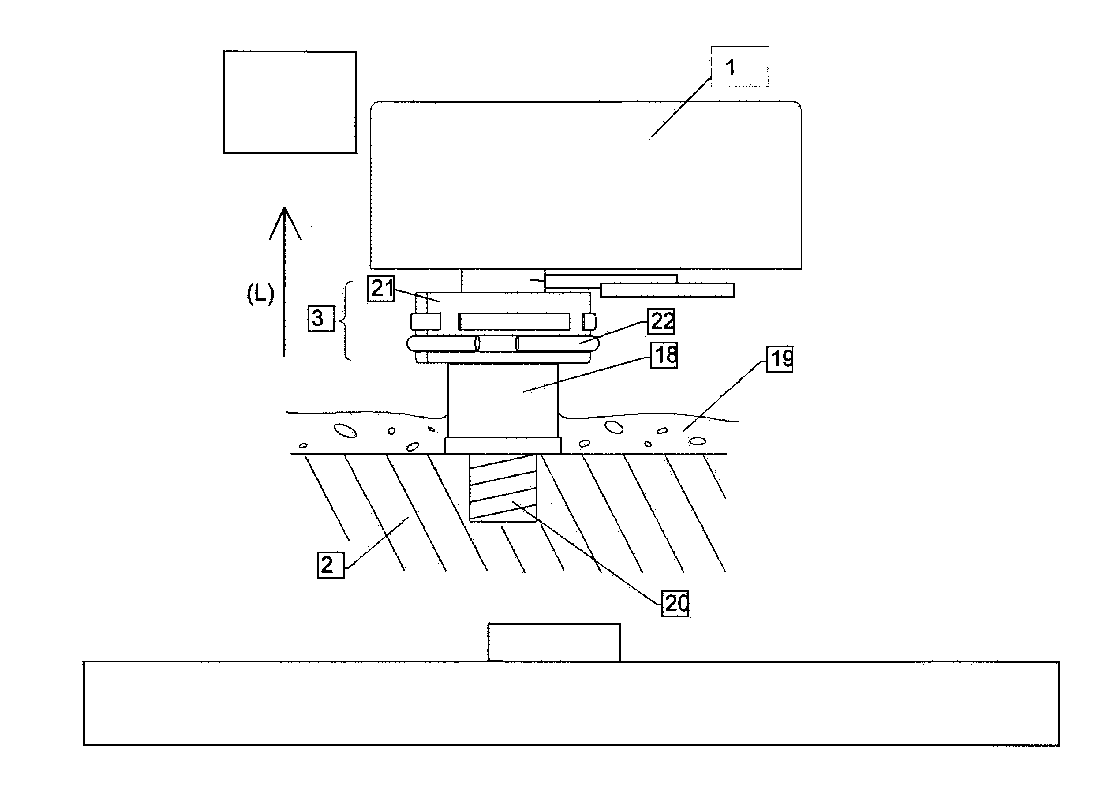
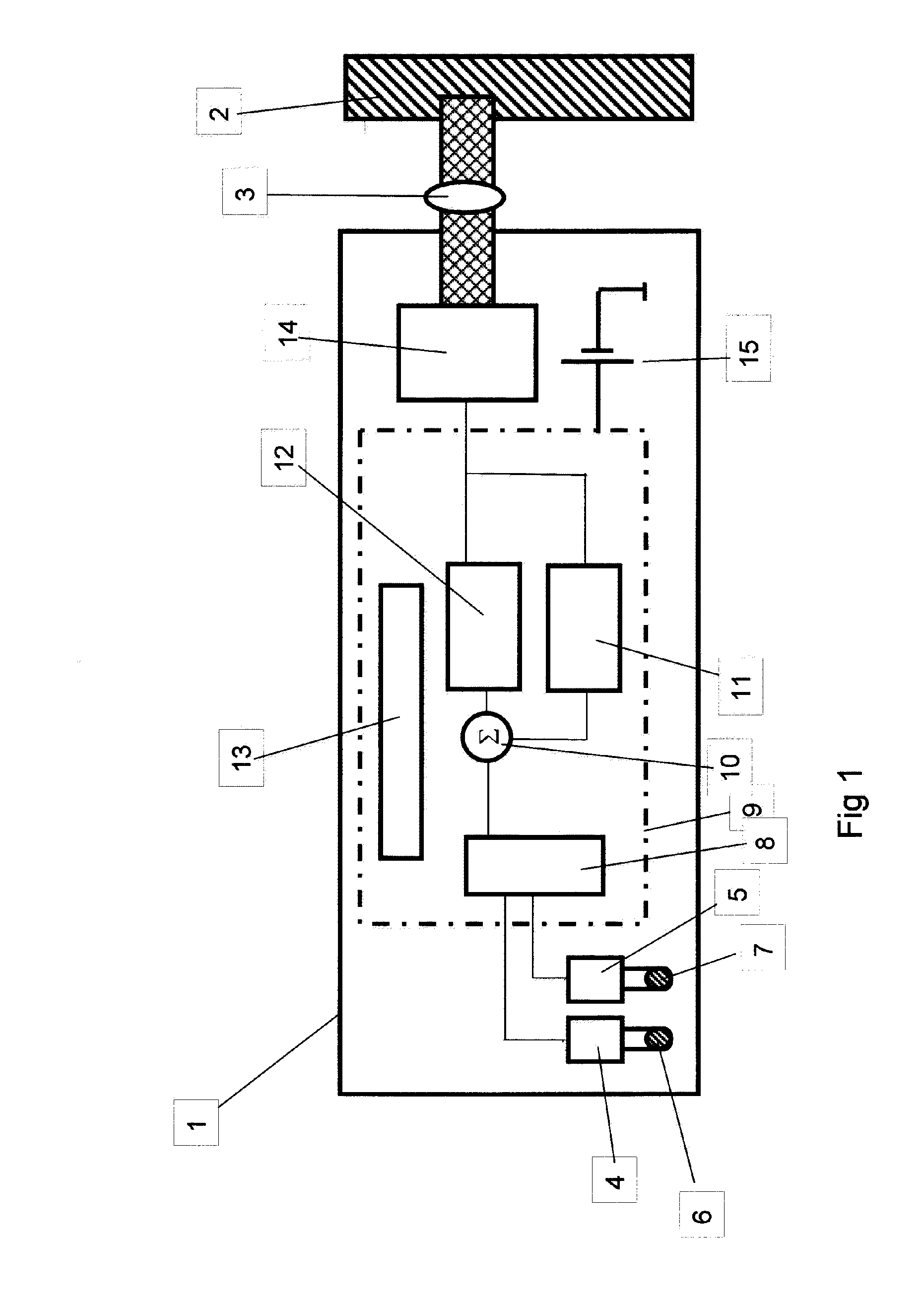
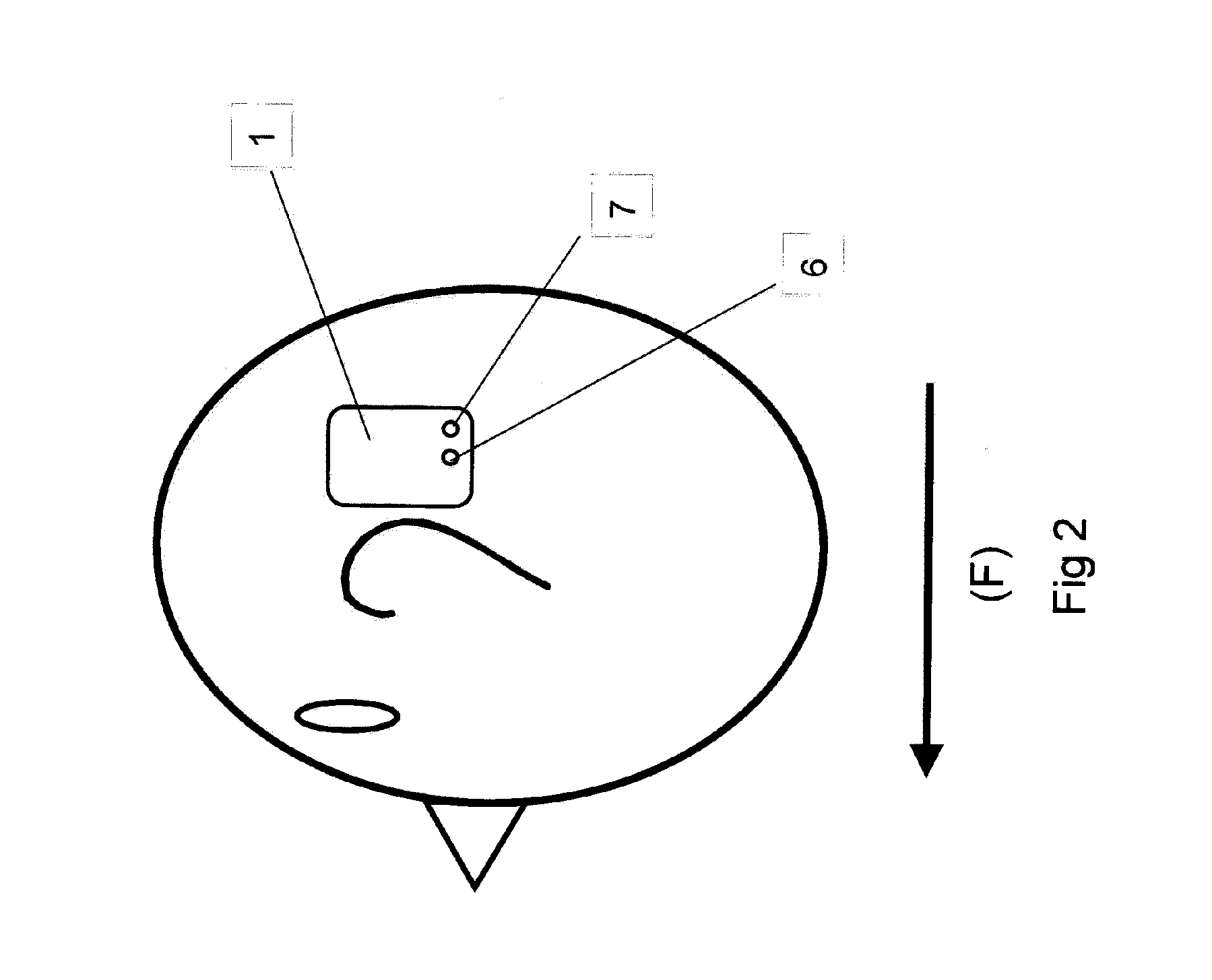
[0021] In FIG. 1, a preferred embodiment of a bone anchored bone conduction hearing aid 1 is shown. The hearing aid is connected to the skull bone via a coupling 4. The hearing aid 1 has a front microphone 4 and a rear microphone 5. The front microphone 4 has a corresponding front sound inlet 6 and the rear microphone 5 has a corresponding rear sound inlet 7. The hearing aid has a microphone processing circuit 8 in the electronic module 9. In a summation circuit 10 the signal from the microphone processing circuit 8 is summarized with the signal from an adaptive feedback cancellation circuit 11. The signal then goes into the amplifier 12. The electronic circuit has a programmable circuit 13 where the sound processing parameters and the processing of the microphone processing circuit can be programmed.

[0022] The signal from the amplifier 12 goes into the vibrator 14. The electronic circuit is powered by a battery 15.

[0023]FIG. 2 shows the front sound inlet 6 and the rear sound inle...


PUM


Abstract

A bone anchored bone conduction hearing aid system comprising two separate microphones connected to two separate inputs of a hearing aid, and a microphone processing circuit in the electronic unit, processing the signals from the two microphones to increase the sound sensitivity for sound coming from the front compared to sound coming from the rear. One of the sound inlets being the frontal sound inlet which is positioned more in the frontal direction (F) than the other sound inlet. The bone anchored bone conduction hearing aid system of the present invention has a programmable microphone processing circuit where the sensitivity for sound coming from the front compared to sound coming from the rear can be varied by programming the circuit digitally in a programming circuit.

Description

TECHNICAL FIELD [0001] The present invention relates to a microphone processing system for a bone anchored bone conduction hearing aid. BACKGROUND OF THE INVENTION [0002] Bone anchored bone conduction hearing aids are essential for the rehabilitation of patients suffering from some specific type of hearing losses for which traditional hearing aids are insufficient. This type of device consists of an external hearing aid with a vibrating transducer which is connected via a connector to a skin penetrating abutment mounted on a fixture anchored in the skull bone. Alternatively this type of devices may have a vibrator implanted under the skin. Typical for all bone anchored bone conduction hearing aids is that the vibrator of the device is firmly mechanically connected to a fixation somewhere in the skull bone. [0003] A bone anchored bone conduction hearing aid has an electronic circuit for amplifying the signal from the microphone. This electronic circuit may be purely analog or may inc...

Claims


Application Information

Patent Timeline
IPC IPC(8): H04R25/00
CPCH04R25/405H04R25/453H04R2225/67H04R2460/13
Inventor WESTERKULL, PATRIK
Owner OTICON
Why Eureka
Try Eureka