Control of respiratory oxygen delivery

Inactive Publication Date: 2006-09-28
MINNESOTA INNOVATIVE TECH & INSTR MITI
View PDF99 Cites 60 Cited by
  • Summary
  • Abstract
  • Description
  • Claims
  • Application Information

AI Technical Summary

Benefits of technology

[0014] The present invention provides respiratory oxygen supply methods and systems. In some aspects, the systems/methods rely on respiration sensors sensing variations in patient respiration to determine when a patient is inhaling and allow for the determination of an inhalation event after exhalation has been determined. In other aspects, the respiration

Problems solved by technology

Continuous oxygen delivery in sub-critical and critical care is, however, wasteful because oxygen is only needed by patients when they are inhaling and the oxygen delivered at other times is wasted.
In supplemental oxygen delivery, the most significant financial cost associated with this waste is found in the increased service visits required by the oxygen provider to replenish the patient's oxygen supply, because the actual cost of the oxygen is only a small fraction of the total cost of the therapy.
It is, however, difficult (if not impossible) to accomplish both of those functions with a single flow sensor because the flow rates that need to be sensed differ by orders of magnitude.
One significant problem is in sensing inhalation or exhalation simultaneously with the delivery of oxygen in these situations.
In addition to the above-listed problems, even if the flow sensor has a dynamic range capable of sensing respiration and delivery oxygen, the systems do not allow for correction in the “drift” often associated with such sensors.
In other words, over time the accuracy of the sensor may be impaired because of dynamic changes in the flow sensor during use.
Because the flow sensors are always in use, monitoring either oxygen flow or respiration, adjustments are difficult if not impossible to make to correct for voltage drift.
One disadvantage to this approach is that if one side of the patient's nasal cavity is blocked due to an upper respiratory infection or cold, the system will either be unable to effectively deliver oxygen or sense respiration (depending on which port of the cannula is located on the blocked side).
Even if the

Method used


Image

  • Control of respiratory oxygen delivery
  • Control of respiratory oxygen delivery
  • Control of respiratory oxygen delivery

Examples


Example

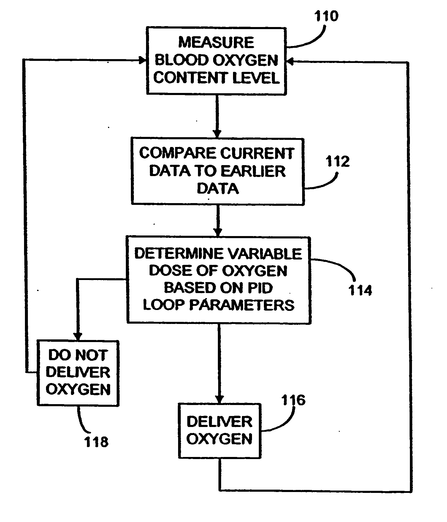
[0031] As described above, the present invention provides demand respirating oxygen supply methods and apparatus for use in sub-acute care which maintain healthy blood oxygen saturation in patients by controlled dosing of oxygen with a measured response to the patient's actual blood oxygen content. The dosing can be provided by simple on / off control over the delivery of oxygen or the amount of oxygen delivered to the patient with each inhalation can be varied in response to the patient's need as determined by a more sophisticated control scheme, such as a proportional-integral-derivative (PID) loop control algorithm, that utilizes the difference between the patient's measured blood oxygen content level and a desired or target blood oxygen content level.

[0032] The systems and methods of the present invention are particularly directed at patients receiving supplemental oxygen in a sub-acute care environment, more preferably in a residential setting. The needs and considerations of pa...


PUM


Abstract

Methods and systems for supplying respiratory oxygen to users when the users are inhaling are disclosed. The methods and systems may rely on delivery devices that are selectively placed in fluid communication with either a respiration sensor or a source of oxygen. The methods and systems may actively monitor for exhalations, as well as monitor for oxygen in the oxygen source. The respiration sensor may preferably be a flow sensor.

Description

RELATED APPLICATIONS [0001] This is a continuation of U.S. patent application Ser. No. 10 / 695,436, filed 28 Oct. 2003, which is a continuation of U.S. patent application Ser. No. 10 / 370,799, filed 20 Feb. 2003, which is a continuation of U.S. patent application Ser. No. 10 / 076,001, filed 14 Feb. 2002, (issued as U.S. Pat. No. 6,561,187), which is a continuation of U.S. patent application Ser. No. 09 / 463,614, filed 25 Jan. 2000 (with a 35 U.S.C. §371 date of May 8, 2000, now issued as U.S. Pat. No. 6,371,114), which is a U.S. National Stage Application of PCT / US98 / 15490, filed 24 Jul. 1998, which claims priority to U.S. Provisional Patent Application Ser. No. 60 / 064,578, filed 4 Nov. 1997 and which also claims priority to (and is a continuation-in-part of) U.S. patent application Ser. No. 08 / 900,686 filed 25 Jul. 1997, (issued as U.S. Pat. No. 6,532,958). All of the above-identified patent applications are incorporated herein by reference in their respective entiretiesFIELD OF THE IN...

Claims


Application Information

Patent Timeline
IPC IPC(8): A61M16/00A62B7/00A61M16/06A61M16/10
CPCA61M16/00A61M2016/0021A61M2016/0024A61M2016/0027A61M2202/03A61M2205/3561A61M2230/205A61M2230/63A61M16/0677A61M16/101A61M16/0051A61M2202/0208A61M16/026A61M2202/0007
Inventor SCHMIDT, MATTHEW F.BUAN, JOHN S.NORDMAN, CATHERINE A.
Owner MINNESOTA INNOVATIVE TECH & INSTR MITI
Why Eureka
Try Eureka