Brake hose

a technology of brake hoses and hoses, which is applied in the direction of flexible pipes, tubular articles, thin material handling, etc., can solve the problems of vapor lock and compromising the pedal feel, and the control of the thickness of the inner tube rubber layer is complicated, so as to achieve high water retention of the material, low volume expansion, and high durability

Inactive Publication Date: 2006-09-28
TOYODA GOSEI CO LTD
View PDF7 Cites 1 Cited by
  • Summary
  • Abstract
  • Description
  • Claims
  • Application Information

AI Technical Summary

Benefits of technology

[0009] In the brake hose of the invention, the rubber material of the inner tube rubber layer and intermediate rubber layer involves the use of a blend in which 40 to 80 wt % is IIR and the rest is EPDM, so as to prevent the penetration of moisture. The upper yarn involves the use of polyvinyl alcohol (PVA) so that the penetration of water into the interior layers can be controlled because of the high water retention of the material. Furthermore, the lower yarn layer is PET, allowing high durability and low volume expansion to be combined. The brake hose can thus reduce the amount of water penetrating from the outside into the interior, while preserving durability and low volume expans

Problems solved by technology

In such environments, moisture from the atmosphere can sometimes penetrate through the outer tube rubber layer 110 into the interior layers and become dissolved in the brake fluid, causing vapor locks and compromising the pedal feel.
Both of these conve

Method used


Image

  • Brake hose
  • Brake hose
  • Brake hose

Examples


Embodiment Construction

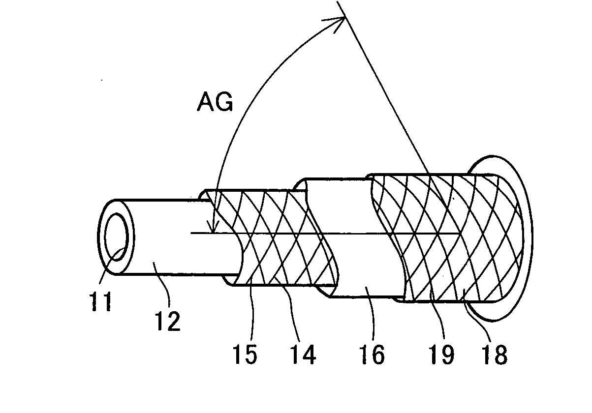
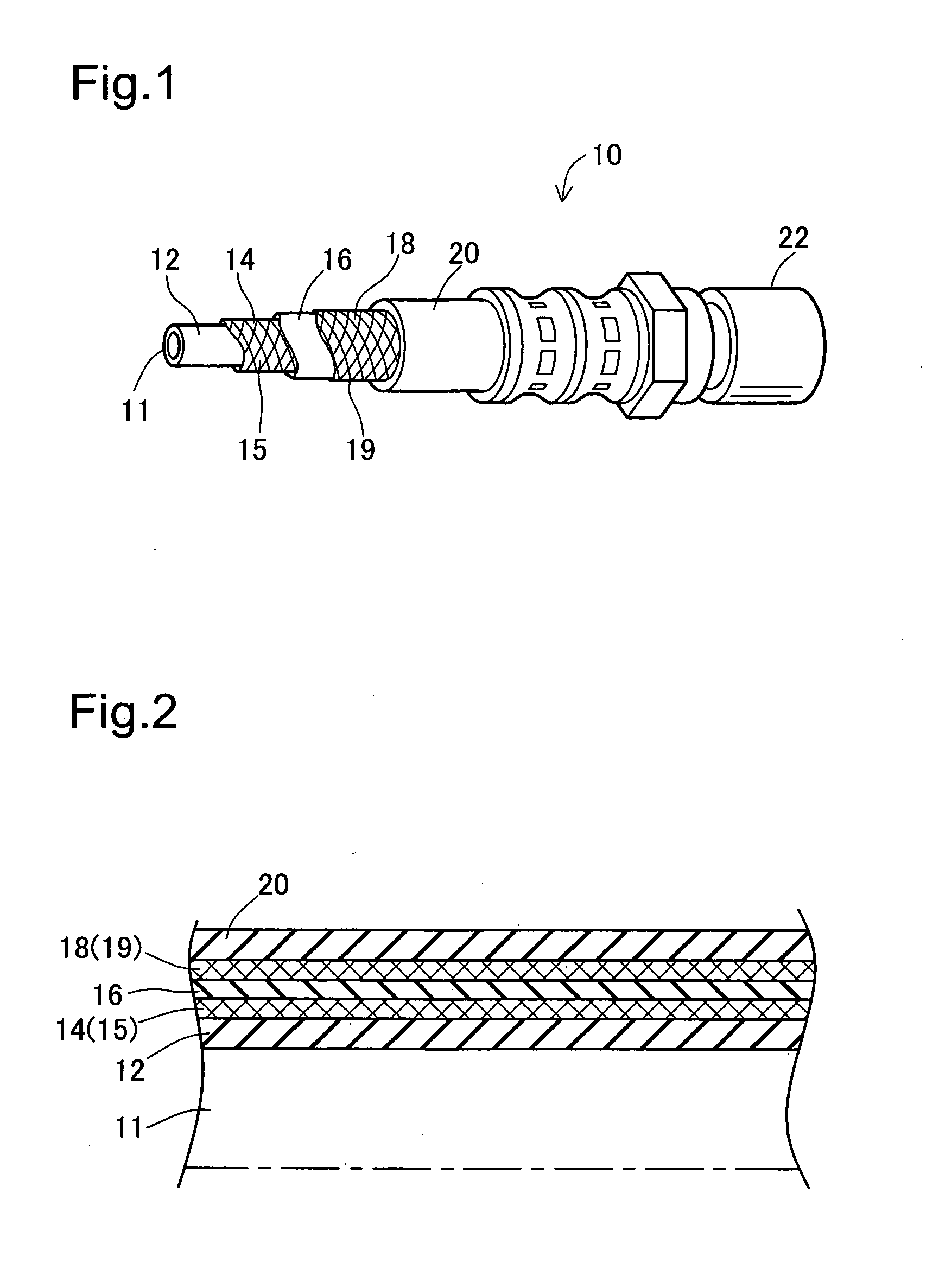
[0023] (1) Schematic Structure of Brake Hose 10

[0024]FIG. 1 is an oblique partial cutaway view of the brake hose 10 in an embodiment of the invention, and FIG. 2 is a half-cross section of the brake hose 10. The brake hose 10 in FIGS. 1 and 2 is used to connect a hydraulic system on the tire side with the master cylinder used in automobile hydraulic brakes (not shown), and is laminated in five layers to withstand the brake fluid pressure. That is, the brake hose 10 has an inner tube rubber layer 12 with a flow path 11, a lower yarn layer 14, an intermediate rubber layer 16, an upper yarn layer 18, and a cover rubber layer 20. The brake hose 10 is joined at the end by tightening a cap 22.

[0025] (2) Structure of Layers in Brake Hose 10

[0026] The materials, thickness, and the like of the layers of the brake hose 10 have been established in order to provide properties such as pressure resistance, durability, expansion resistance, and water penetration resistance to allow the hose to wi...


PUM


Abstract

A brake hose is made by laminating an inner tube rubber layer, lower yarn layer, intermediate rubber layer, upper yarn layer, and cover rubber layer. The rubber material of the inner tube rubber layer and intermediate rubber layer is a blend material in which 40 to 80 wt % is IIR and the remainder is EPDM. The upper yarn is PVA, and the upper yarn is PET, where the tensile strength per unit decitex is at least 6.5 g, and the 2.7 g elongation is 2.6±1%. The brake hose has better water penetration resistance and can be produced by a general purpose method.

Description

[0001] This application claims the benefit of and priority from Japanese Application No. 2005-88347 filed Mar. 25, 2005, the content of which is incorporated herein by reference. BACKGROUND OF THE INVENTION [0002] 1. Field of the Invention [0003] The invention relates to a brake hose formed by the lamination of a plurality of rubber layers and reinforcing layer, which is used in automobiles and the like. [0004] 2. Description of the Related Art [0005] A conventional brake hose used in automobiles is described in JP-A-63-303,288 or JP-A-6-305,083 (see FIG. 11). FIG. 11 is a cross section of the main components of a conventional brake hose 100. The brake hose 100 is formed by laminating several layers of rubber and yarn layers because of the need for high pressure resistance against brake hydraulics. That is, the brake hose 100 is formed by laminating an inner tube rubber layer 102 forming a flow path 101 for flowing brake oil, a lower yarn layer 104, an intermediate layer 106, an upp...

Claims


Application Information

Patent Timeline
IPC IPC(8): F16L11/00
CPCY10T428/1393F16L11/086
Inventor FURUI, KENICHIROMIZUTANI, SATOSHIOKUHARA, SHIGEKIKONDO, NORIYUKI
Owner TOYODA GOSEI CO LTD
Why Eureka
Try Eureka