Glass-forming die and method

a technology of metallic dies and glass, applied in glass tempering equipment, foundry patterns, moulding apparatus, etc., can solve the problems of defective bottle formation, limited ability to change the distance, and insufficient plastic parison, so as to improve the heat removal of that region, improve the control of heat removal, and improve the uniformity of heat removal

Inactive Publication Date: 2006-09-28
HOWMET CORPORATION
View PDF5 Cites 45 Cited by
  • Summary
  • Abstract
  • Description
  • Claims
  • Application Information

AI Technical Summary

Benefits of technology

[0009] The present invention provides a glass-forming die having features for improving control of heat removal from the die to thereby provide a desired temperature profile, uniform or non-uniform, of glass material molded in the die body.
[0010] Pursuant to an embodiment of the invention, the glass-forming die comprises a die body having a molding surface with a curved contour to form at least a portion of a glass article to be made. The die body includes one or more cooling passages through which a cooling fluid passes inside the body to remove heat. In one embodiment, the cooling passage(s) is/are non-linear (non-straight) along at least a portion of its/their length in a manner to improve uniformity of heat removal from the die body when the cooling fluid passes therethrough. Alternately, the cooling passage(s) can be non-linear (non-straight) along at least a portion of its/th...

Problems solved by technology

If too much heat is removed, the parison will not be plastic enough to be formed to final shape in the final or finish die, resulting in formation of a defective bottle.
If too little heat is removed, the parison may be too plastic during transfer to the final or finish die.
Consequently, the distance from the cooling holes or passages to the blank mold cavity surface (and therefore the molten glass) varies considerably along the length of the blank mold and the ability to change that distance is extremely limited.
The application of the lubricant is a...

Method used


Image

  • Glass-forming die and method
  • Glass-forming die and method
  • Glass-forming die and method

Examples


Embodiment Construction

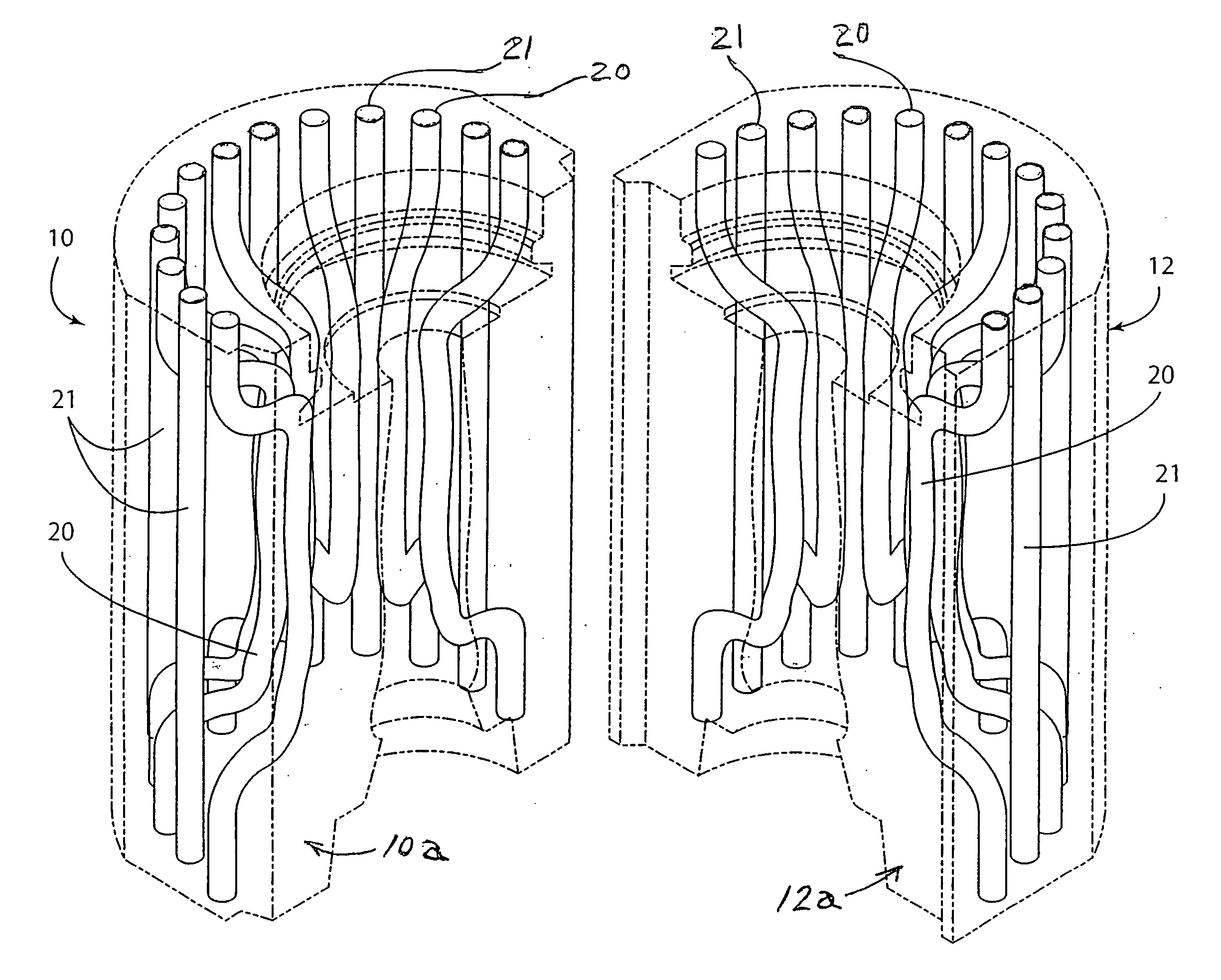
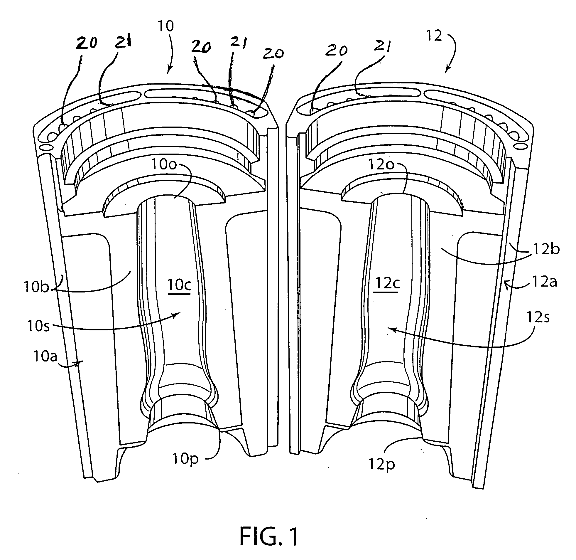
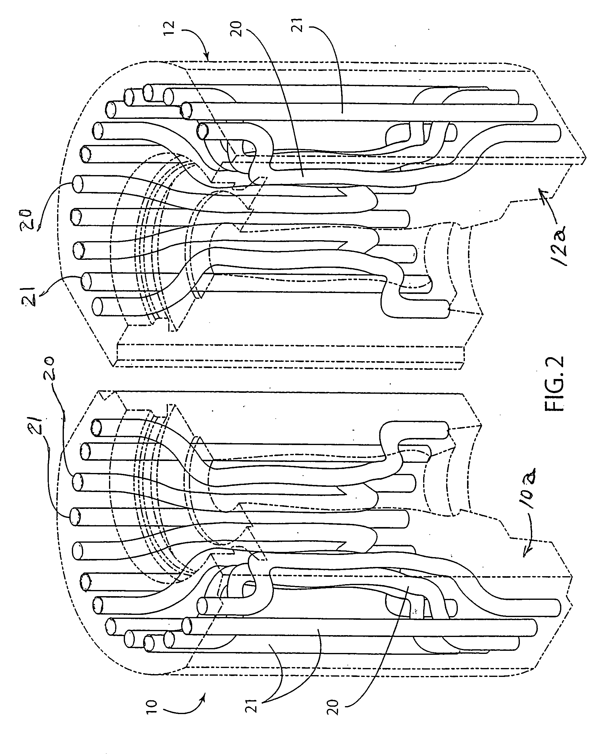
[0021] Referring to FIGS. 1 and 2, a pair of parison-forming dies 10, 12 known as ‘blank’ molds are shown for molding a ‘gob’ of molten glass to form a parison therebetween in the bottle making process described above. The dies 10, 12 include respective die bodies 10a, 12a having surfaces 10b, 12b which mate and contact together when the dies are closed or pressed together in a bottle making machine.

[0022] The die bodies include respective mold cavity regions 10c, 12c that form a complete molding cavity having the three dimensional shape of the parison when the dies 10, 12 are closed or pressed together in the bottle making machine. The mold cavity regions are defined by respective molding surfaces 10s, 12s on the die bodies 10a, 12a. As is shown in FIG. 1, the molding surfaces each has a curved contour to collectively form a portion of the curved outer surface of the parison. In practice of the invention, the molding surfaces 10s, 12s optionally can be provided with a coating that...


PUM

PropertyMeasurementUnit
Grain sizeaaaaaaaaaa
Temperatureaaaaaaaaaa
Lengthaaaaaaaaaa

Abstract

Glass-forming die, such as a parsain-forming or bottle-forming die, includes a die body having a molding surface with a curved contour to form at least a portion of a glass bottle or other article to be made. The die body has one or more cooling passages inside the body wherein the cooling passages is/are non-linear (non-straight) along at least a portion of their length to improve temperature control of the die during the glass forming operation. To this end, the cooling passages are curved in a manner to generally follow the curved contour along at least a portion of the length of the curved contour, and may include heat radiating or turbulating elements in the cooling passage. The glass-forming die alternately, or in addition, can include integral cooling fins, ribs or other heat radiating element on one or more exterior regions of the die.

Description

[0001] This application claims benefits and priority of provisional application Ser. No. 60 / 660,919 filed Mar. 11, 2005.FIELD OF THE INVENTION [0002] The present invention relates to a glass-forming metallic die and method providing improved cooling of the glass-forming surface of the die. BACKGROUND OF THE INVENTION [0003] Current glass bottle molding processes consist of three main steps. First, a small portion of glass, called a ‘gob’, drops in a pre-measured amount from a liquid glass holding tank above a high speed glass bottle forming machine. This gob falls into a die called a ‘blank’ mold, which is typically made of cast iron. The blank mold includes a cavity to receive the glass gob and configured to form an intermediate bottle shape known as a parison. The parison is then removed from the blank mold and moved to a final or finish die having a cavity with the final bottle shape and markings to be imparted to the bottle. In the final or finish die, the parison is blown using...

Claims


Application Information

Patent Timeline
IPC IPC(8): B22D7/10C03B9/38C03B9/48C03B11/12
CPCB22C7/02B22C9/04B22C9/065B22C9/10B22C9/24B22D29/002C03B9/3875C03B9/48C03B11/12
Inventor VOGT, RUSSELL G.MURPHY, KENNETH S.HE, JOHNHRUBEC, ROBERT J.COLE, GAIL R.GRUNSTRA, ROBERT E.
Owner HOWMET CORPORATION
Why Eureka
Try Eureka