Light emitting apparatus

Active Publication Date: 2006-09-28
SEIKO EPSON CORP
View PDF2 Cites 45 Cited by
  • Summary
  • Abstract
  • Description
  • Claims
  • Application Information

AI Technical Summary

Benefits of technology

[0008] An advantage of the invention is that it provides a light emitting apparatus where a lower-layer-side reflecting layer used for an optical resonator and disposed at a lower-layer side of each of positive electrodes does not deteriorate even in case of forming different thicknesses of the positive electrodes according to pixels and an electronic apparatus having the light emitting apparatus.
[0009] According to an aspect of the present invention, there is provided a light emitting apparatus having light emitting devices having a stack of a light-transmitting anode, a functional layer including at least a light emitting layer, and a cathode for a plurality of pixels corresponding to red, green, and blue colors on a substrate, wherein an optical resonator having a lower-layer-side reflecting layer at a lower-layer side of the anode is formed in the light emitting device, wherein a plurality of the pixels include pixels which correspond to different thicknesses of a anode, and wherein a light-transmitting insulating protective film is formed between the anode and the lower-layer-side reflecting layer to cover the lower-layer-side reflecting layer.
[0010] In addition, since a plurality of the pixels include pixels which correspond to different thicknesses of the anode, although the etching processes are performed several times when the anode is formed, according to the invention, the light-transmitting insulating protective film covering the lower-layer-side reflecting layer is disposed between the anode and the lower-layer-side reflecting layer, after the lower-layer-side reflecting layer is formed, although any times of the etching processes are performed to form the anode, the etching cannot cause deterioration of the lower-layer-side reflecting layer.
[0011] In the aforementioned aspect, the lower-layer-side reflecting layer may have a total reflecting property, and light generated by the light emitting layer may emit to an opposite side of the substrate as seen from the light emit

Problems solved by technology

Therefore, in order to form different thicknesses of the positive electrodes for the red, green, and blue pixels, the aforementioned process is needed to repeat thee times. As a result, there is a problem in that, since the lower-layer-

Method used


Image

  • Light emitting apparatus
  • Light emitting apparatus
  • Light emitting apparatus

Examples


first embodiment

Basic Construction of Light Emitting Apparatus

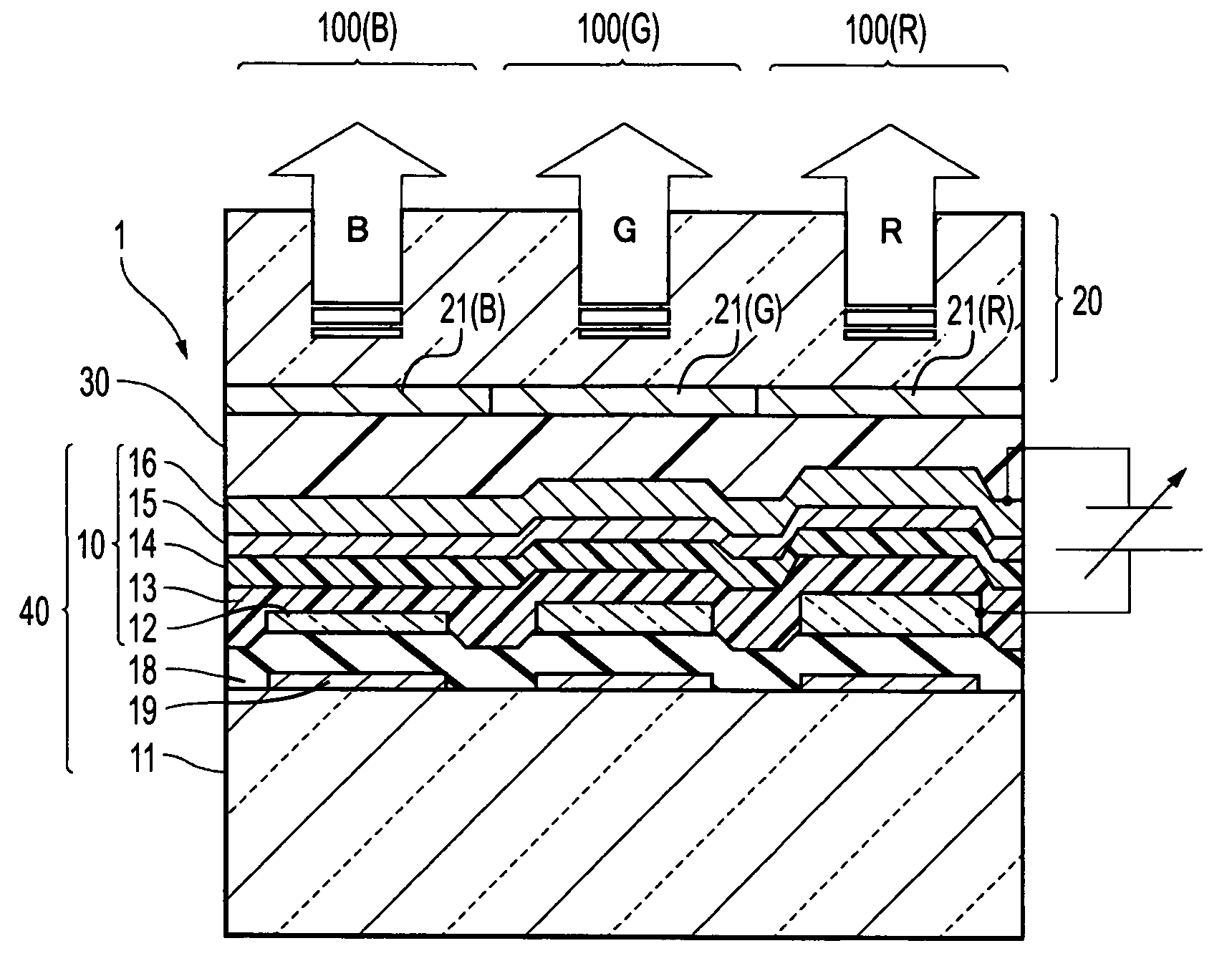
[0025]FIG. 1 is a schematic cross sectional view showing an organic EL device (light emitting device) used for an organic EL apparatus (light emitting apparatus) according to a first embodiment of the invention.

[0026] In FIG. 1, the organic EL apparatus 1 according to the embodiment is a top emission type apparatus which emits display light to an opposite side of a substrate 11, and an organic EL device 10 is formed for each of red (R), green (G), and blue (B) pixels 100 (R), (G), and (B). The organic EL device 10 has a construction formed by sequentially stacking a transparent anode 12 made of ITO or the like, a hole transport layer 13, and a cathode 16 made of a magnesium-silver alloy and having a semi-transparent reflecting property on an upper-layer side of the substrate 11 made of a glass or the like.

[0027] In addition, a reflecting layer 19 (a total reflecting layer) made of aluminum, an aluminum alloy, silver, or a silver allo...

second embodiment

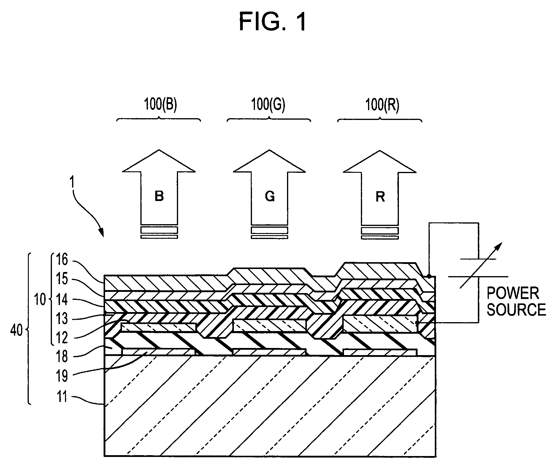
[0048]FIG. 2 is a schematic cross sectional view showing an organic EL device (light emitting device) used for an organic EL apparatus (light emitting apparatus) according to a second embodiment of the invention.

[0049] Similarly to the first embodiment, the organic EL apparatus 1 shown in FIG. 2 is a top emission type apparatus which emits display light to an opposite side of a substrate 11, and an organic EL device 10 is formed for each of red (R), green (G), and blue (B) pixels 100 (R), (G), and (B). The organic EL device 10 has a construction formed by sequentially stacking a transparent anode 12 made of ITO or the like, a hole transport layer 13, and a cathode 16 made of a magnesium-silver alloy and having a semi-transparent reflecting property on an upper-layer side of the substrate 11 made of a glass or the like. In addition, a reflecting layer 19 (a total reflecting layer) made of aluminum, an aluminum alloy, silver, or a silver alloy is formed between the substrate 11 and t...


PUM


Abstract

A light emitting apparatus having light emitting devices having a stack of a light-transmitting anode, a functional layer including at least a light emitting layer, and a cathode for a plurality of pixels corresponding to red, green, and blue colors on a substrate, wherein an optical resonator having a lower-layer-side reflecting layer at a lower-layer side of the anode is formed in the light emitting device, wherein a plurality of the pixels include pixels which correspond to different thicknesses of a anode, and wherein a light-transmitting insulating protective film is formed between the anode and the lower-layer-side reflecting layer to cover the lower-layer-side reflecting layer.

Description

BACKGROUND [0001] 1. Technical Field [0002] The present invention relates to a light emitting apparatus and an electronic apparatus having a light emitting device such as an organic EL device. [0003] 2. Related Art [0004] Much attention has been paid to display apparatus used for electronic apparatuses such as a mobile phone, a personal computer, and a PDA (Personal Digital Assistant) or light emitting apparatuses such as an organic EL (Electroluminescence) apparatus used as an exposing head in an image forming apparatus such as a digital copier and a printer. Conventionally, when such kinds of light emitting apparatuses are constructed as a color type, light of each color emits from each pixel by varying materials constituting a light emitting layer for each pixel. [0005] On the other hand, there has been proposed a technique for extracting light of each color from an emitting light of the light emitting device by disposing an optical resonator between a lower-layer-side reflecting...

Claims


Application Information

Patent Timeline
IPC IPC(8): H05B33/00H01L51/50
CPCH01L27/3211H01L27/322H01L51/5206H01L51/5265H01L2251/5315H01L2251/558H10K59/35H10K59/38H10K50/81H10K50/852H10K50/856H10K2102/3026H10K2102/351F16B2/065F16L3/1025
Inventor MAEDA, TSUYOSHIMATSUMOTO, TOMOTAKA
Owner SEIKO EPSON CORP
Why Eureka
Try Eureka