

Optical low-pass filter
- Summary
- Abstract
- Description
- Claims
- Application Information
AI Technical Summary
Benefits of technology
Problems solved by technology
Method used
Image

Examples
first embodiment
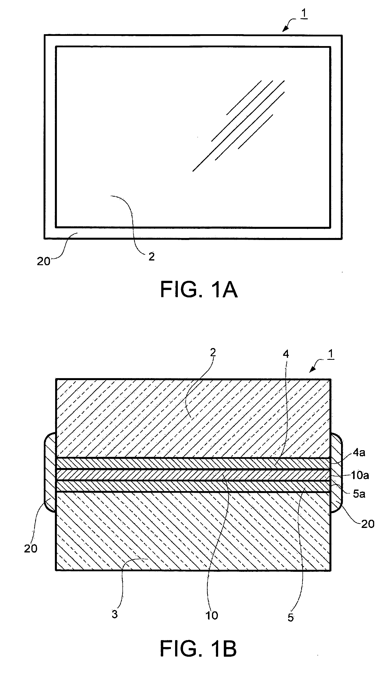
[0035]FIG. 1A is a plan view of an optical low-pass filter 1 in a first embodiment and FIG. 1B is a sectional view of the optical low-pass filter 1.
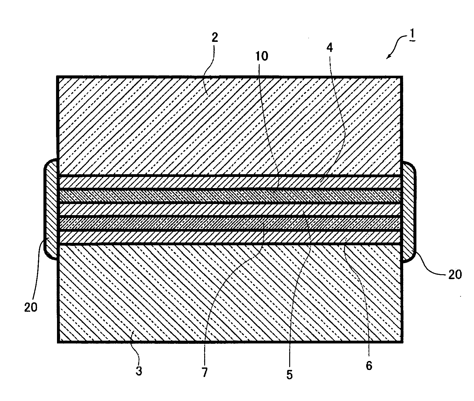
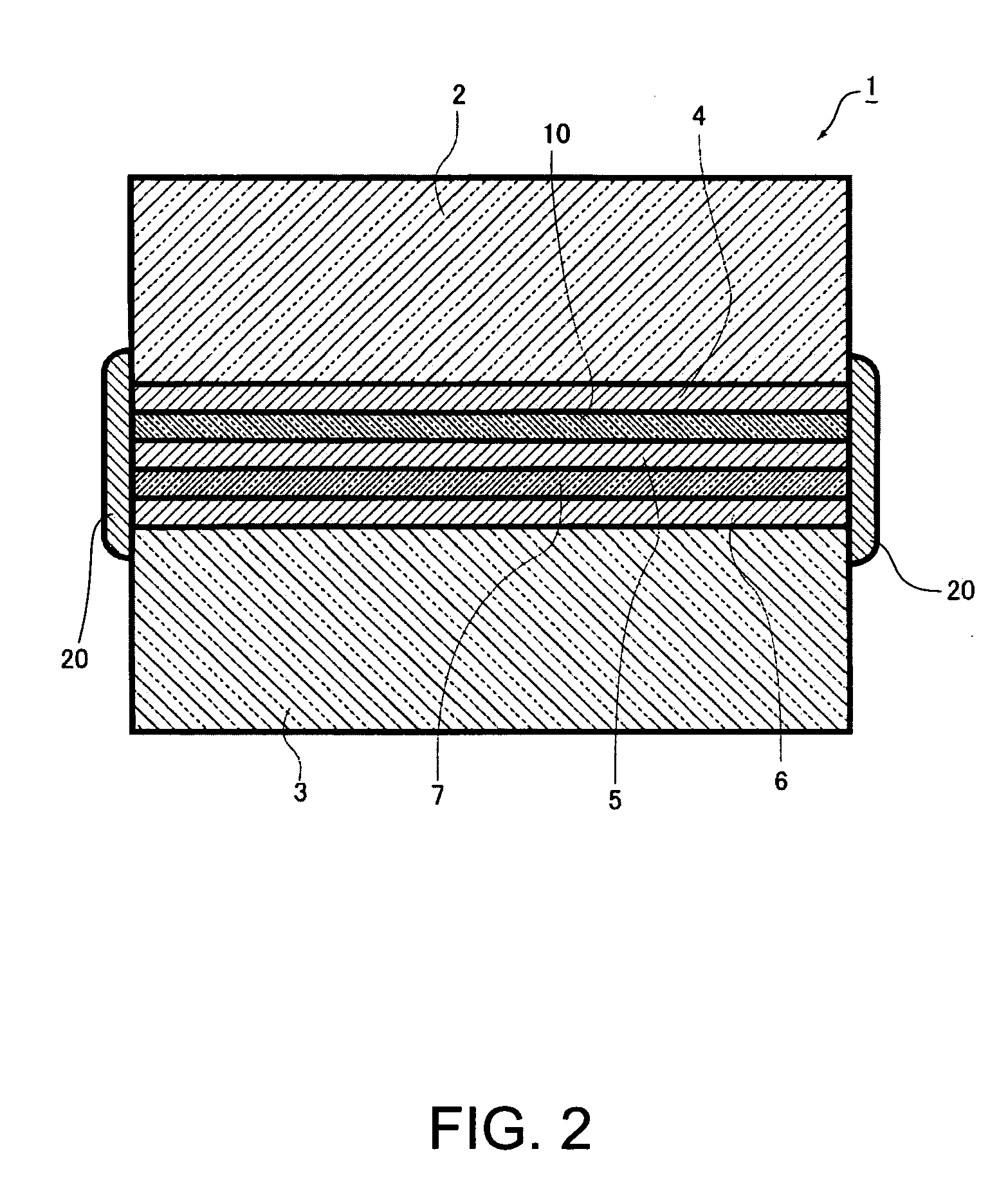
[0036] With tacky layers 4 and 5 and a retardation film 10 made of a polymer film as a quarter-wave plate adhered between quartz plates 2 and 3 as birefringent plate, and, with an entire region including at least an external peripheral border 4a of the tacky layer 4, an external peripheral border 5a of the tacky layer 5 and an external peripheral border 10a of the retardation film 10 covered, a sealing portion 20 is disposed.
[0037] The quartz plates 2 and 3 as birefringent plate may be made of, other than quartz, a crystal plate having the birefringence such as lithium niobate (LiNbO3). Only quartz plate may be used for both, quartz and lithium niobate may be combined, or birefringent plate constituted of other materials may be combined. The birefringence means a phenomenon where incident light is separated into two lights of an ordina...
second embodiment
[0053]FIG. 3 is a sectional view showing a schematic configuration of an optical low-pass filter according to a second embodiment. A principal configuration of the optical low-pass filter is substantially same as that shown in FIG. 2; accordingly, like elements are given with like numbers and descriptions thereof will be omitted. The optical low-pass filter according to the second embodiment is different from that shown in FIG. 2 in that, instead of the sealing portion 20, a water-repelling portion 21 that is obtained by processing an external periphery surface of the optical low-pass filter where external peripheral borders of tacky layers 4, 5 and 6 are exposed with a water repelling agent while covering entire external peripheral borders of the tacky layers 4, 5 and 6 and the retardation film 10 and furthermore an entire external periphery surface of the infrared absorption filter plate 7 is disposed. The water-repelling portion 21 covers entire external peripheral borders of the...
third embodiment
[0072] In an optical low-pass filter according to a third embodiment, an external peripheral border of a phase plate is partially located inside of an external peripheral border of at least one birefringent plate of two birefringent plates to form a step or a recess. By making use of the step or recess, a sealing portion is formed.
[0073]FIG. 4A is a plan view of an optical low-pass filter 1 in example 1 of the third embodiment and FIG. 4B is a sectional view of the optical low-pass filter 1.
[0074] A quartz plate 2 as a birefringent plate is formed smaller than a quartz plate 3 as a birefringent plate. When tacky adhesives 4 and 5 and a polymer retardation film 10 as a quarter-wave plate are adhered, the quartz plate 2 is adhered inside of the quartz plate 3 so that the difference of the sizes of the quartz plates 2 and 3 may generate steps 3a, 3b, 3c and 3d. The steps 3a, 3b, 3c and 3d each may be different from each other. In the steps 3a, 3b, 3c and3d where the external peripher...
PUM
 Abstract
Description
Claims
Application Information