System for control of gas injectors
- Summary
- Abstract
- Description
- Claims
- Application Information
AI Technical Summary
Benefits of technology
Problems solved by technology
Method used
Image

Examples
example 1
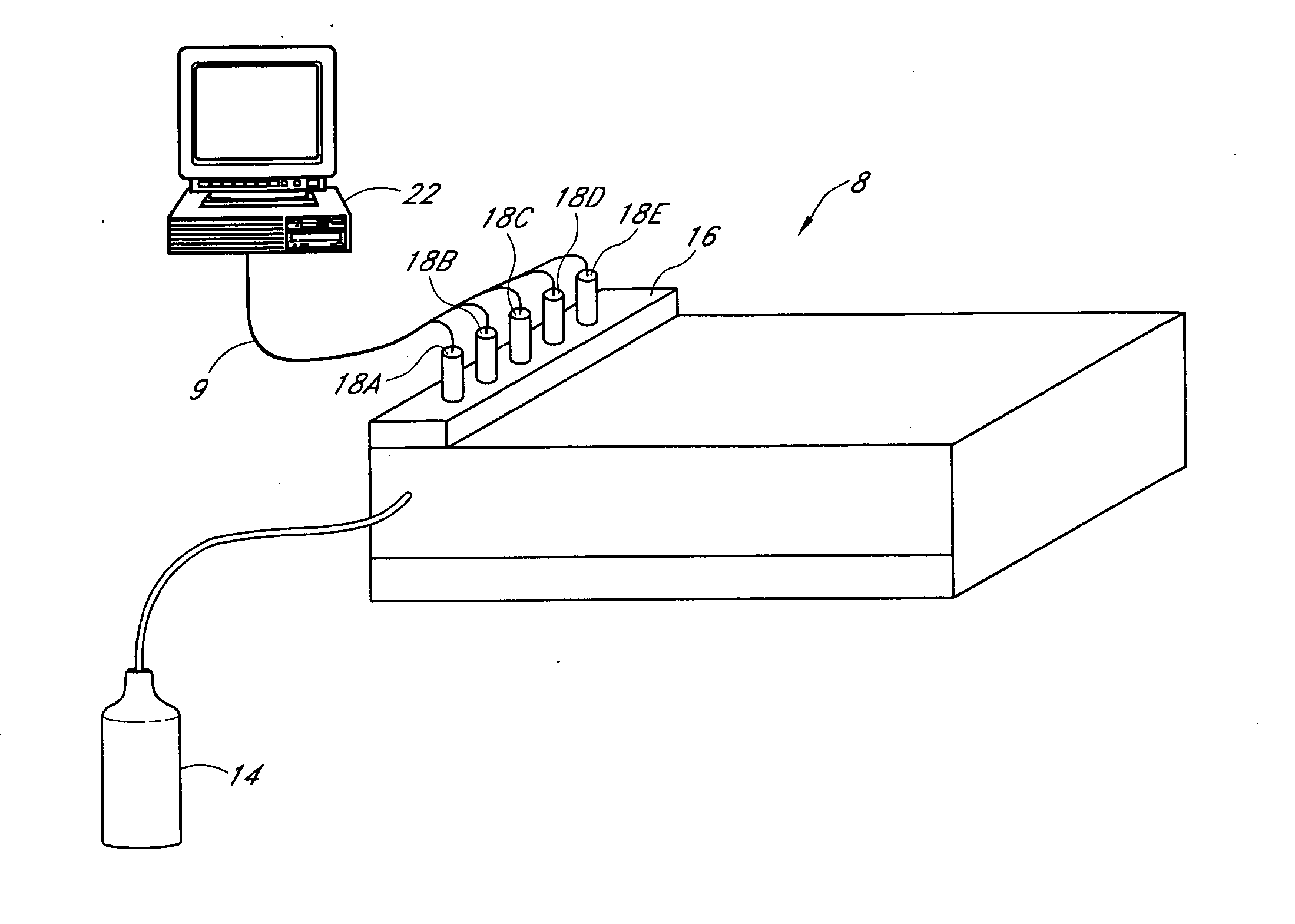
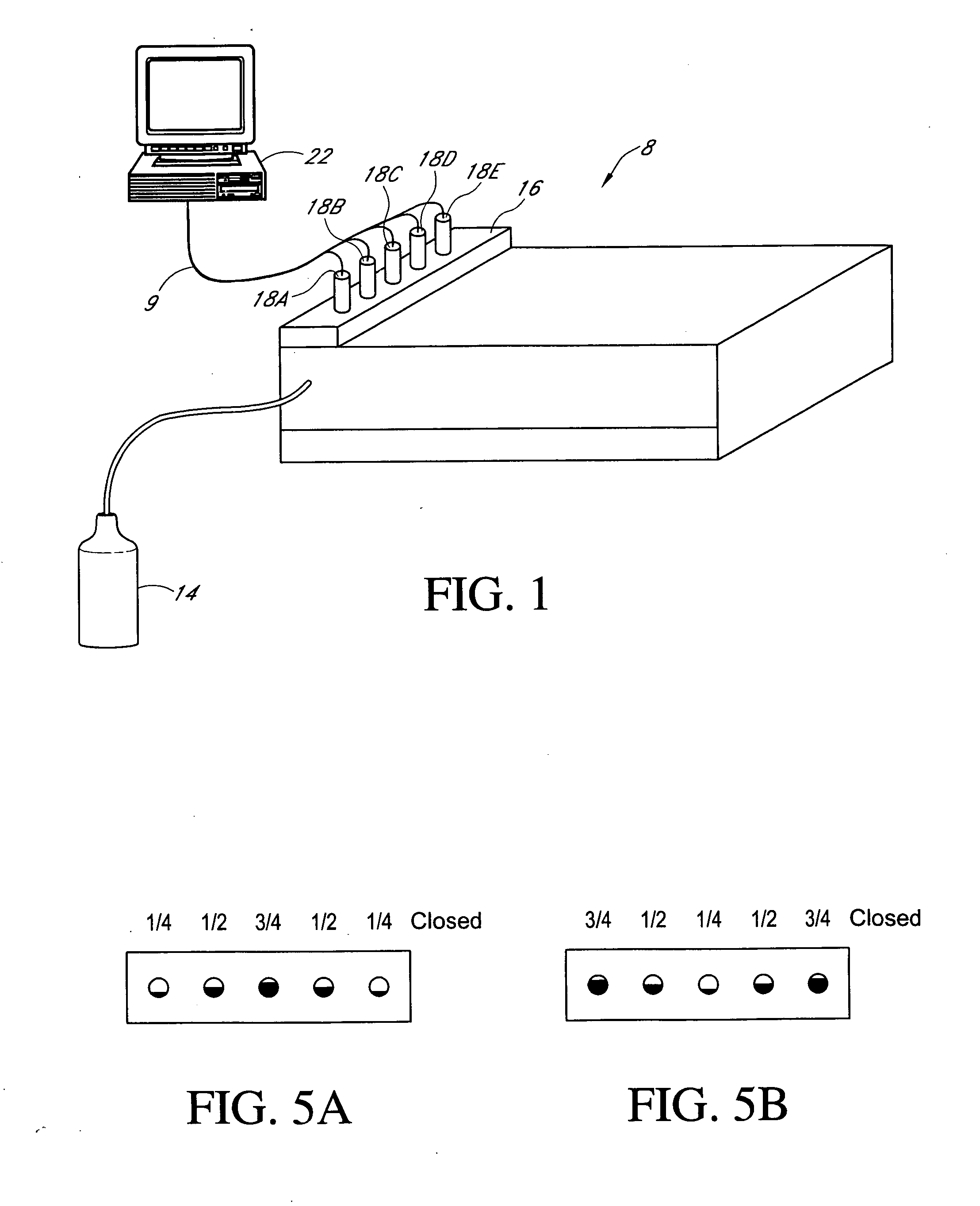
[0064] A substrate is loaded into an Epsilon® E-3000 reactor chamber, commercially available from ASM America, Inc. of Phoenix, Ariz., under a flow of 20 slm of ultra high purity (UHP) H2 atmospheric pressure. The wafer is then rotated at 35 rpm and the temperature is increased to 950° C. The substrate is allowed to stabilize under these conditions for 2 minutes and the pressure is then reduced to 40 Torr while maintaining the 20 slm UHP H2 flow. The substrate temperature is then reduced to 630° C. and allowed to stabilize under these conditions. Throughout these steps, the injectors are set using computer control, as follows:
InjectorSetting11.6021.8032.0041.8051.60
[0065] A flow of 50 sccm H2 / Si3H8 (“Gas A”), which is formed in a bubbler maintained at 21° C., 4 PSIG pressure, is then added to the flow of 20 slm H2 and directed over the substrate and into the exhaust for 30 seconds to deposit an epitaxial silicon film that is 100 Å thick. The thickness non-uniformity of the silicon...
example 2
[0067] Example 2 includes the steps outlined in Example 1, but includes the following modifications: A flow of 10 sccm of H3CSiH3 (20%, balance H2) (“Gas C”) and a flow of 30 sccm of B2H6 (100 PPM, balance H2) (“Gas D”), are added during the Si80Ge20 deposition step with injector settings of:
InjectorSetting18A1.8318B2.0918C2.2518D2.0918E1.83
[0068] The concentrations of the components in the layer resulting from Gas C and Gas D (i.e., carbon and boron, respectively) are highly uniform throughout the film thickness as measured by electrical measurements (i.e., 4 point probe for boron and high resolution X-Ray diffraction for carbon).
example 3
[0069] Example 3 includes the steps outlined in Example 1, but includes the following modifications below in order to deposit a multilayer structure, including graded layers.
[0070]FIG. 7 shows a graphical representation of the injector settings during the process of Example 3 over time, in one embodiment.
[0071] The flow of Gas B is ramped from 0 sccm to 80 sccm into the chamber over 15 seconds, while the injectors are ramped from their initial settings to their final settings over 15 seconds:
InjectorInitial SettingFinal Setting18A1.601.7518B1.802.0018C2.002.1518D1.802.0018E1.601.75
[0072] The flows of Gas A and Gas B from Example 1 and H2 are maintained to the chamber for 30 seconds. The flow of Gas B is then ramped from 80 sccm to 40 sccm while the injectors are ramped from their initial to their final settings over 20 seconds:
InjectorInitial SettingFinal Setting18A1.751.7018B2.001.9518C2.152.1018D2.001.9518E1.751.70
[0073] While maintaining the flow of Gas A and Gas B to vent ...
PUM
| Property | Measurement | Unit |
|---|---|---|
| Time | aaaaa | aaaaa |
| Time | aaaaa | aaaaa |
| Time | aaaaa | aaaaa |
Abstract
Description
Claims
Application Information