Wireless communication system

a communication system and wireless technology, applied in the field of wireless communication systems, can solve the problems of difficult to consider the beam direction in other cells, difficult to perform real-time processing, etc., and achieve the effect of improving the efficiency of the downstream radio channel and suppressing radio interferen

Inactive Publication Date: 2006-09-28
HITACHI LTD
View PDF0 Cites 42 Cited by
  • Summary
  • Abstract
  • Description
  • Claims
  • Application Information

AI Technical Summary

Benefits of technology

[0022] A wireless communication system according to the present invention can suppress radio interference between base stations and can improve the efficiency of the downstream radio channel.

Problems solved by technology

Because each base-station apparatus independently performs packet scheduling to select a mobile station to be connected by wireless communication, it is hard to consider the beam directions in other cells.
If a plurality of base stations determine the beam regions of the cells by sharing information determining the radio-wave transmission regions, it would be tough to perform real-time processing because of delay and data amounts in data transfer between the apparatuses.

Method used


Image

  • Wireless communication system
  • Wireless communication system
  • Wireless communication system

Examples


first embodiment

1. First Embodiment

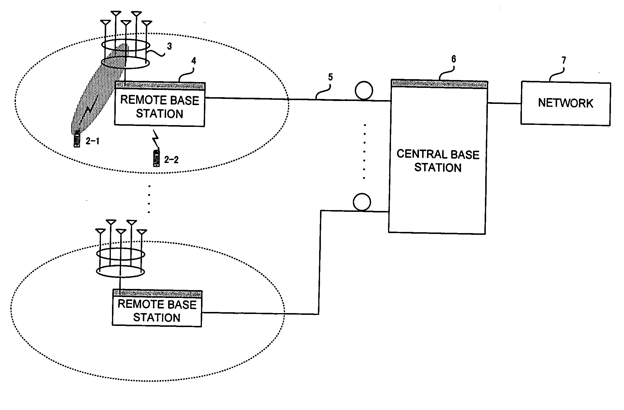
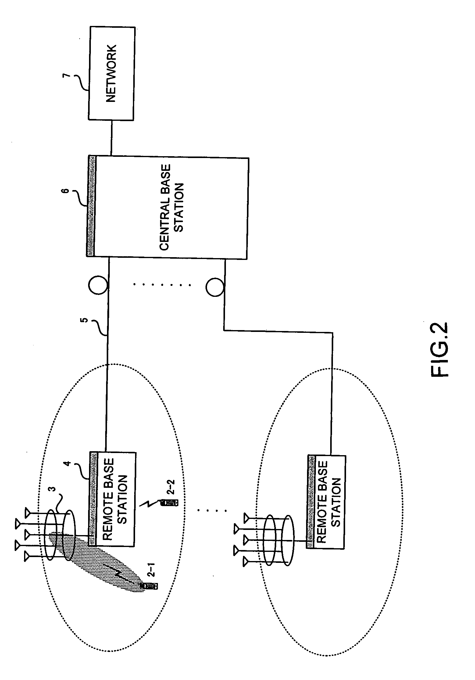
[0042]FIG. 2 shows the configuration of a first embodiment of the present invention. As shown in the figure, a central base station 6 is connected to a network 7 and also to a plurality of remote base stations 4 through fiber-optic cables 5. The remote base station 4 perform wireless communication with a mobile station 2-1 selected from a plurality of mobile stations 2-1 to 2-2, by using a radio-wave beam formed by a direction-variable antenna 3.

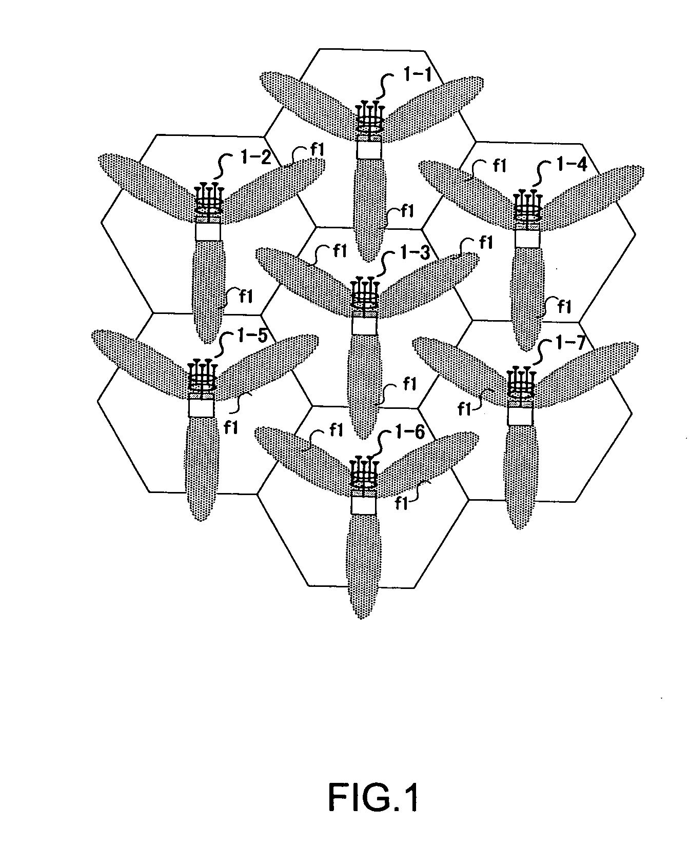
[0043]FIG. 3 shows a layout of remote base stations 4 placed in cells. The central base station 6 controls a plurality of remote base stations 4-1 to 4-7 so that they send narrow-aperture radio-wave beams in the same frequency band of f1 in such directions that interference will not occur. The beam transmission directions can be switched at predetermined times so that communication can be performed with the mobile stations in all directions.

[0044]FIG. 4 shows a block diagram of the remote base station 4, which has the wi...

second embodiment

2. Second Embodiment

[0067] Another embodiment of the present invention will be described. The second embodiment differs from the first embodiment in that the central base station performs scheduling on the basis of information calculated by a mobile station. More specifically, the mobile station generates area information for the mobile station management table and also generates interference evaluation information. This enables a table to be created in accordance with the quality of radio waves received by the mobile station and thus enables the precision of scheduling for avoiding interference to be improved. The mobile station calculates the information by using a pilot signal sent by the remote base station periodically in each area.

[0068]FIG. 17 shows a block diagram of a mobile station of the second embodiment. The mobile station includes an antenna module 3, a duplexer (DUP) 8, a radio-frequency receiver (RX) 9, a demodulator (DEM) 17, a decoder (DEC) 18, an encoder (COD) 21...


PUM


Abstract

A wireless communication which suppresses radio interference between wireless base stations and improves the channel efficiency is implemented. In the wireless communication system including a central base station, a plurality of remote base stations having a direction-variable antenna, and a plurality of mobile stations to communicate with the remote base stations, the central base station performs centralized management of radio-wave beam patterns to be sent to the plurality of mobile stations which will communicate with remote base stations and performs packet scheduling of the mobile stations in such a manner that radio waves sent from the remote base stations will not cause strong interference at the mobile stations.

Description

BACKGROUND OF THE INVENTION [0001] 1. Field of the Invention [0002] The present invention relates to wireless communication systems, and more specifically, to a wireless communication system which includes a plurality of cells and is suited for suppressing radio interference from adjacent base stations. [0003] 2. Description of the Related Art [0004] In a CDMA cellular system, the base stations of adjacent cells use radio waves in the same frequency band. Radio interference can occur between those cells. The degree of interference depends on the propagation environment and the positional relationship between the base stations. Interference provides an insufficient signal-to-interference (S / I) ratio, and high-speed data transmission becomes impossible sometimes. Accordingly, stable communication must be established by increasing the processing gain, using a modulation system having a high degree of noise immunity, such as BPSK, or the like. A sufficiently high S / I ratio allows the pr...

Claims


Application Information

Patent Timeline
Patent Type & Authority Applications(United States)
IPC IPC(8): H04M1/00H04B1/7097H04B7/10H04J13/00H04W4/00H04W16/28
CPCH04B7/0408H04B7/0617H04W16/26H04W16/28H04W28/10H04W64/006
Inventor UWANO, KOKITAIRA, MASANORIFUJISHIMA, KENZABUROKUWAHARA, MIKIO
Owner HITACHI LTD
Why Eureka
Try Eureka