System for assembly of a rotating machine

a technology for rotating machines and assembly systems, which is applied in the direction of data acquisition and logging, instruments, and static/dynamic balance measurement. it can solve the problems of reducing the clearance, affecting the relative position of the rotor and the casing, and affecting the operation of the machin

Active Publication Date: 2006-09-28
MITSUBISHI HEAVY IND LTD
View PDF4 Cites 12 Cited by
  • Summary
  • Abstract
  • Description
  • Claims
  • Application Information

AI Technical Summary

Benefits of technology

[0011] It is an object of the present invention to provide a system for assembly of a rotating machine which, in an assembly work of a large rotating machine, can specify measuring points to measure an amount of misalignment between a rotor and a casing and can record the measurement results being obtained at the specified measuring points as data. In addition, it is another object of the present invention to provide a system for assembly of a rotating machine which can automatically do calculations for correction of the measurement results being obtained at non-measurable points. Moreover, it is another object to provide a system for assembly of a rotating machine which can automatically calculate the measurement results of misalignment and the measurement results at the non-measurable points for correction, and at the same time, can indicate an optimum amount of adjustment based on the results of the calculations for correction.
[0016] In accordance with the present invention, because measuring points necessary for each work process of an assembly work are instructed by an input terminal unit, a worker can confirm measuring points in each work process easily by referring to instructions of the input terminal unit. In addition, because the input terminal unit determines whether measured values and predicted values of measurement at each measuring point are within a permissible design range or not, a worker can confirm assembly positions easily that are out of the permissible design range by referring to information of the input terminal unit. Moreover, because measured values at the measuring points are recorded in the database for each work process, measured values in each work process during assembly can be easily confirmed by referring to the data being stored in the database after a rotating machine is completely assembled.
[0017] Furthermore, in the input terminal unit in accordance with the present invention, because a predicted value of measurement at a non-measurable second measuring point is obtained and an amount of adjustment is specified to adjust the position of a rotor or a casing based on measured values or predicted values of measurement at the measuring points, conventional calculation being performed by a worker become unnecessary, which eliminates cumbersome of an assembly work. Additionally, because weighting addition being provided with a weighting coefficient based on the positions of the measuring points is performed, more accurate and optimum amount of adjustment can be obtained.

Problems solved by technology

However, due to a decrease in the clearances, when each of the shaft centers of the casing serving as a stationary part and the rotor serving as a rotating part is slightly out of alignment, edges of the stationary vanes and rotating blades being installed to the casing and the rotor, respectively, come into contact with the casing and the rotor.
As a result, due to the contacts as have been mentioned, there is a fear of breakage of a rotating machine when the rotating machine is rotated.
However, in each process of (1) when a rotor is assembled to the lower half of an inner casing, (2) when the upper half of the inner casing is assembled, (3) when the upper half of an outer casing is assembled, and (4) when all parts are assembled, deflection and distortion of the rotor and the casing occur based on the empty weight and rigidity thereof, which consequently changes the relative positions of the rotor and the casing.
Therefore, conventionally, it is necessary for a worker to check each measurement part, and there is a potentiality that missing of measurement might occur.
However, because different workers do the calculations for correction for each point, activities thereof become cumbersome.
Hereat, it is necessary to determine parameters for the calculations for correction, based on the empty weight and rigidity of the casing and the rotor of a large rotating machine to be assembled, which further makes activities of the calculations for correction cumbersome and complicated.

Method used


Image

  • System for assembly of a rotating machine
  • System for assembly of a rotating machine
  • System for assembly of a rotating machine

Examples


Embodiment Construction

[0034] Referring now to the drawings, an embodiment of the present invention will be described hereinafter. The following embodiment will be explained with a gas turbine, representing a large rotating machine, but the same is applied to other large rotating machines such as a steam turbine and the like.

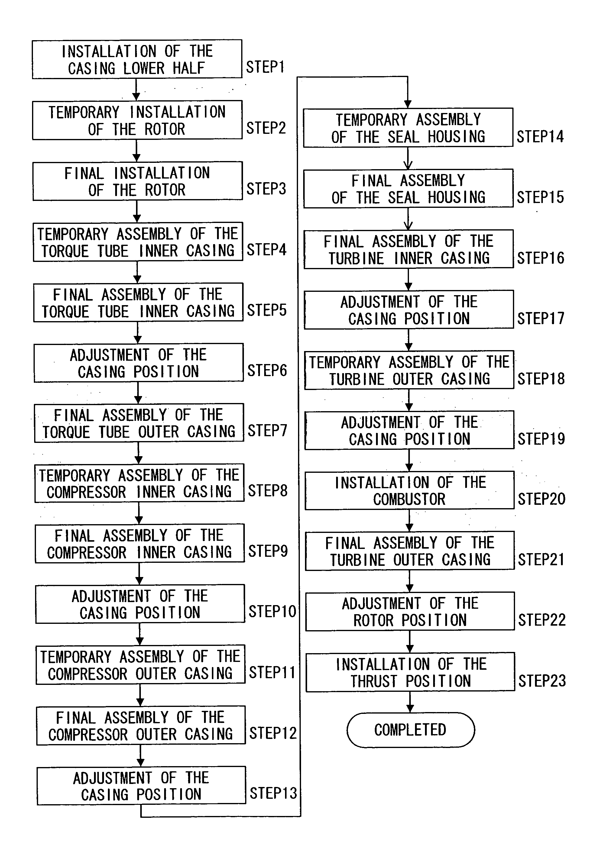
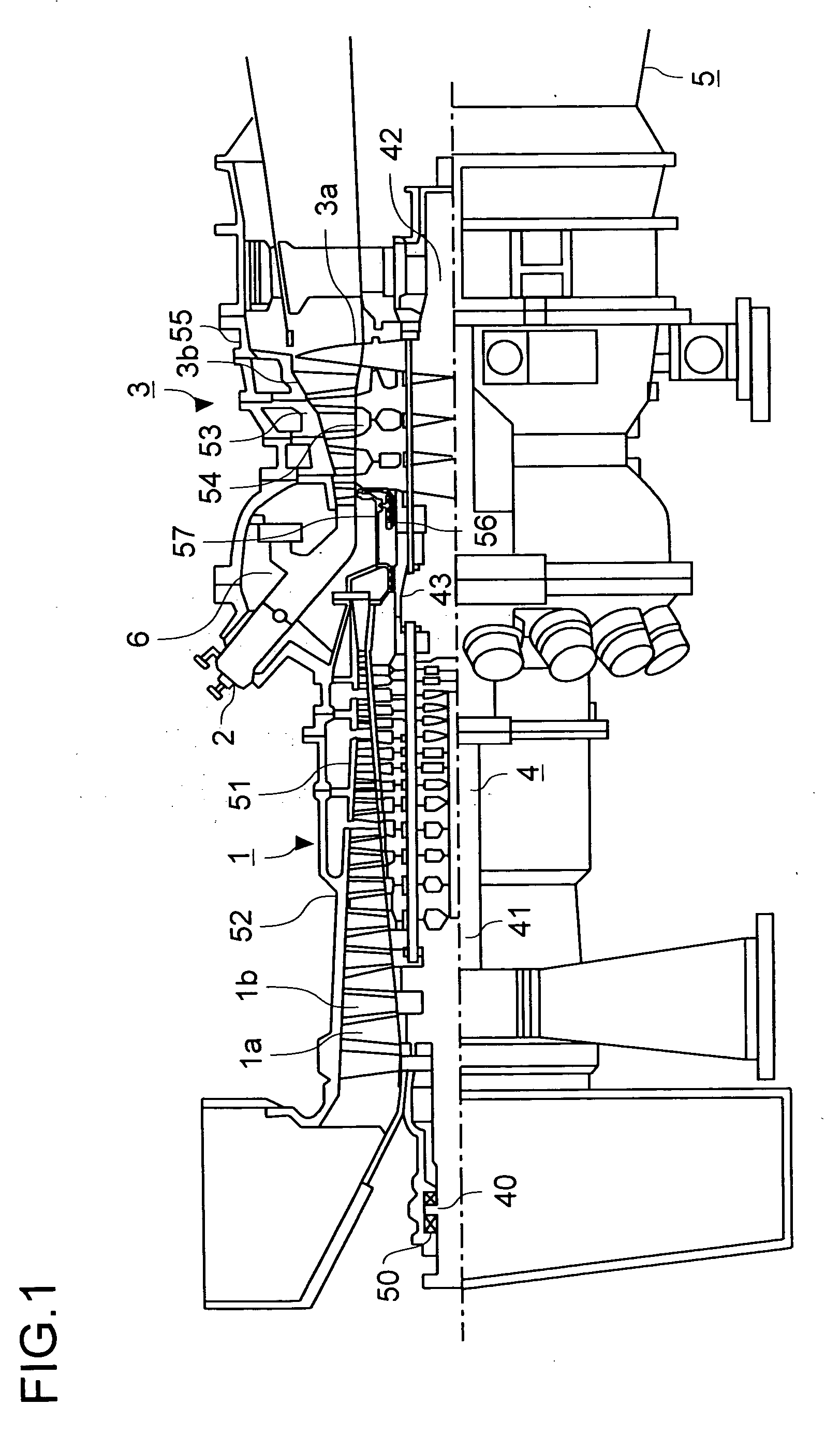
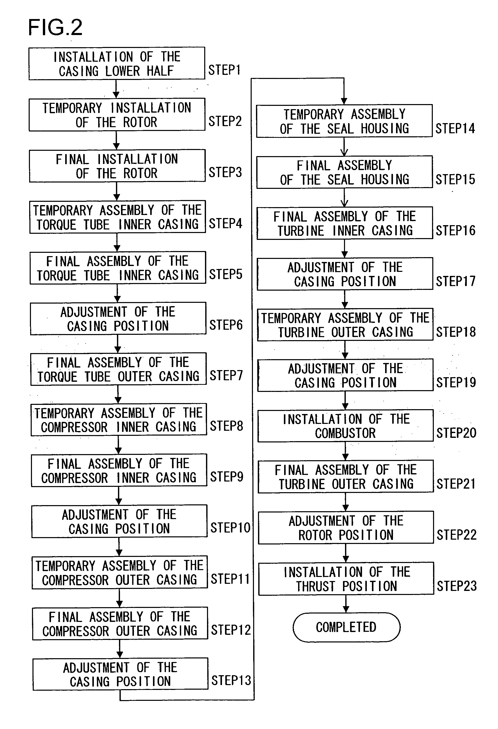
[0035] First of all, an assembly work of a gas turbine will be simply explained by referring to the drawings. FIG. 1 is a schematic cross-sectional view along the axial direction of a rotor showing an outline construction of a gas turbine. In addition, FIG. 2 is a flow chart showing an outline of the assembly work of a gas turbine.

[0036] A gas turbine in FIG. 1 comprises a compressor 1 compressing air from the outside; a combustor 2 being supplied with the air compressed in the compressor 1 and performing combustion behavior with a fuel and the air being supplied; and a turbine 3 being rotary driven by combustion gas being generated by combustion behavior of the combustor 2. Then, t...


PUM


Abstract

In each work process of the assembly work of a large rotating machine, an input terminal unit 101 displays measuring points necessary for measurements of radial and axial clearances between a rotor and a casing so as to provide workers with instructions. When workers measure the clearances at the instructed measuring points, the measured values will be supplied to the input terminal unit 101 so as to confirm whether the measured values are within design tolerances or not. In addition, when workers measure the clearances at the instructed measuring points, amounts of adjustment of the casing will be displayed so that the measurement results at the measuring positions will have an optimum positional relation with the designed values.

Description

[0001] The present invention is based on the Japanese Patent Application No. 2005-87807 filed on Mar. 25, 2005, the contents of which are hereby incorporated by reference. BACKGROUND OF THE INVENTION [0002] 1. Field of the Invention [0003] The present invention relates to a system for assembly of a rotating machine to perform data processing of measurements of each portion in an assembly work of a large rotating machine such as a gas turbine, a steam turbine and the like. [0004] 2. Description of the Prior Art [0005] Generally, in order to assemble a large rotating machine such as a gas turbine, a steam turbine and the like, a lower half of each of an outer casing and an inner casing thereof is placed on a base stand being installed with a predetermined levelness. Then, after a rotor is installed to the lower half of the inner casing being placed, the upper half of the inner casing is assembled to the upper side of the lower half of the inner casing so as to cover the rotor, and sub...

Claims


Application Information

Patent Timeline
Patent Type & Authority Applications(United States)
IPC IPC(8): G01B3/00
CPCB23P19/04F01D25/00F05D2230/60F05D2260/80F05D2230/50
Inventor HOLI, SHUJITAKASUGI, YUKIKO
Owner MITSUBISHI HEAVY IND LTD
Why Eureka
Try Eureka