
Heat energy recovery apparatus

a heat energy recovery and apparatus technology, applied in mechanical apparatus, engine components, machines/engines, etc., can solve problems such as bending, torsional force, strain in the heat energy recovery apparatus, and achieve the effect of relieving tensile stress and/or compressive stress, and improving conventional drawbacks

Inactive Publication Date: 2006-10-05
TOYOTA JIDOSHA KK
View PDF15 Cites 20 Cited by
  • Summary
  • Abstract
  • Description
  • Claims
  • Application Information

AI Technical Summary

Benefits of technology

[0011] Consequently, the present invention is to improve such conventional drawbacks and it is an object of the present invention to provide a heat energy recovery apparatus capable of relieving tensile stress and / or compressive stress generated with thermal expansion of a heat source.
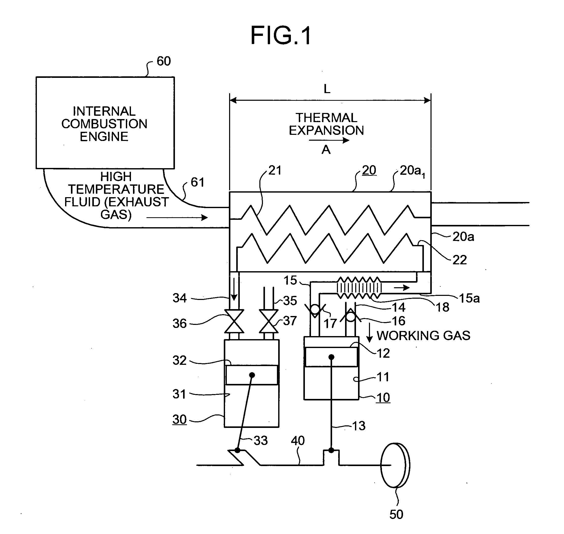
[0015] According to this heat energy recovery apparatus, when the heat exchanger expands thermally, pressure is applied to the first extending unit in the same direction as that of the thermal expansion and therefore tensile stress generated in the working gas exhaust path can be relieved; when the exhaust flow path of the internal combustion engine expands thermally, pressure is applied to the first extending unit in the same direction as that of the thermal expansion and therefore tensile stress generated in the working gas supply path can be relieved.
[0017] According to this heat energy recovery apparatus, when the heat exchanger expands thermally, the first extending unit (bellows) extends in the same direction as that of the thermal expansion and therefore tensile stress generated in the working gas exhaust path can be efficiently absorbed. When the exhaust flow path of the internal combustion engine expands thermally, the first extending unit (bellows) extends in the same direction as that of the thermal expansion and therefore tensile stress generated in the working gas supply path can be efficiently absorbed.
[0021] The heat energy recovery apparatus according to the present invention, as described above, even when the exhaust flow paths of the heat exchanger and the internal combustion engine expand thermally, tensile stress or compressive stress generated in the working gas exhaust pipe of the compressor and in the working gas supply path of the expander can be absorbed or relieved and therefore bends, torsions, or the like generated in the working gas exhaust pipe and the working gas supply path can be suppressed. Furthermore, concurrently, bends, torsions, or the like generated in a connecting rod and crankshaft of the compressor and expander can also be suppressed. Consequently, according to the heat energy recovery apparatus of the present invention, strains generated in the heat energy recovery apparatus can be suppressed and therefore damages thereof can be avoided.

Problems solved by technology

Especially, the tensile stress and / or compressive stress occur in the aforementioned interconnecting pipings of the compressor and expander, resulting in causing bends, torsions, or the like in the interconnecting pipings.
Then, such bends and torsions cause strains in the heat energy recovery apparatus.

Method used


Image

  • Heat energy recovery apparatus
  • Heat energy recovery apparatus
  • Heat energy recovery apparatus

Examples


first embodiment

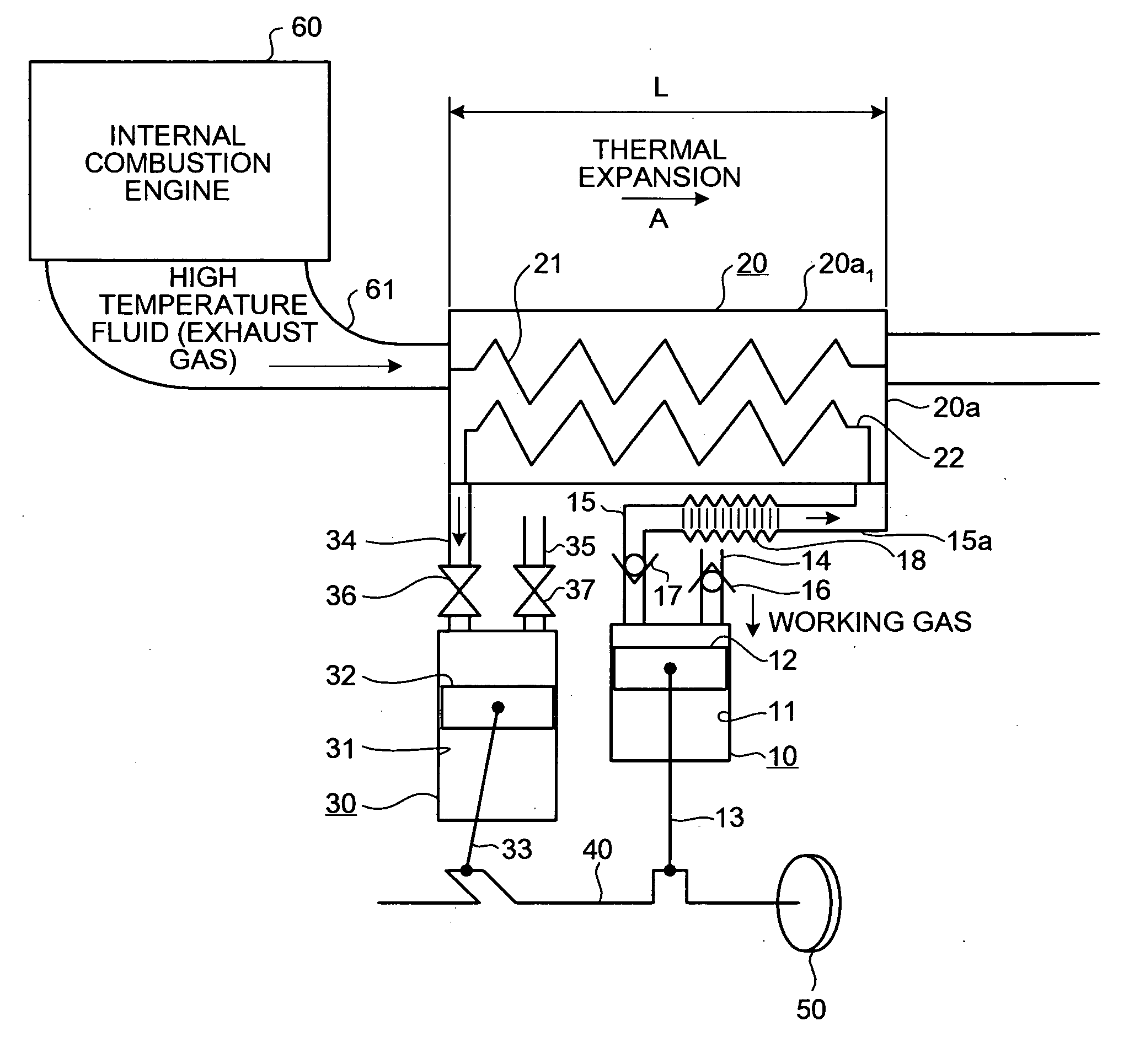
[0031] A heat energy recovery apparatus according to the present invention will be described with reference to FIG. 1.

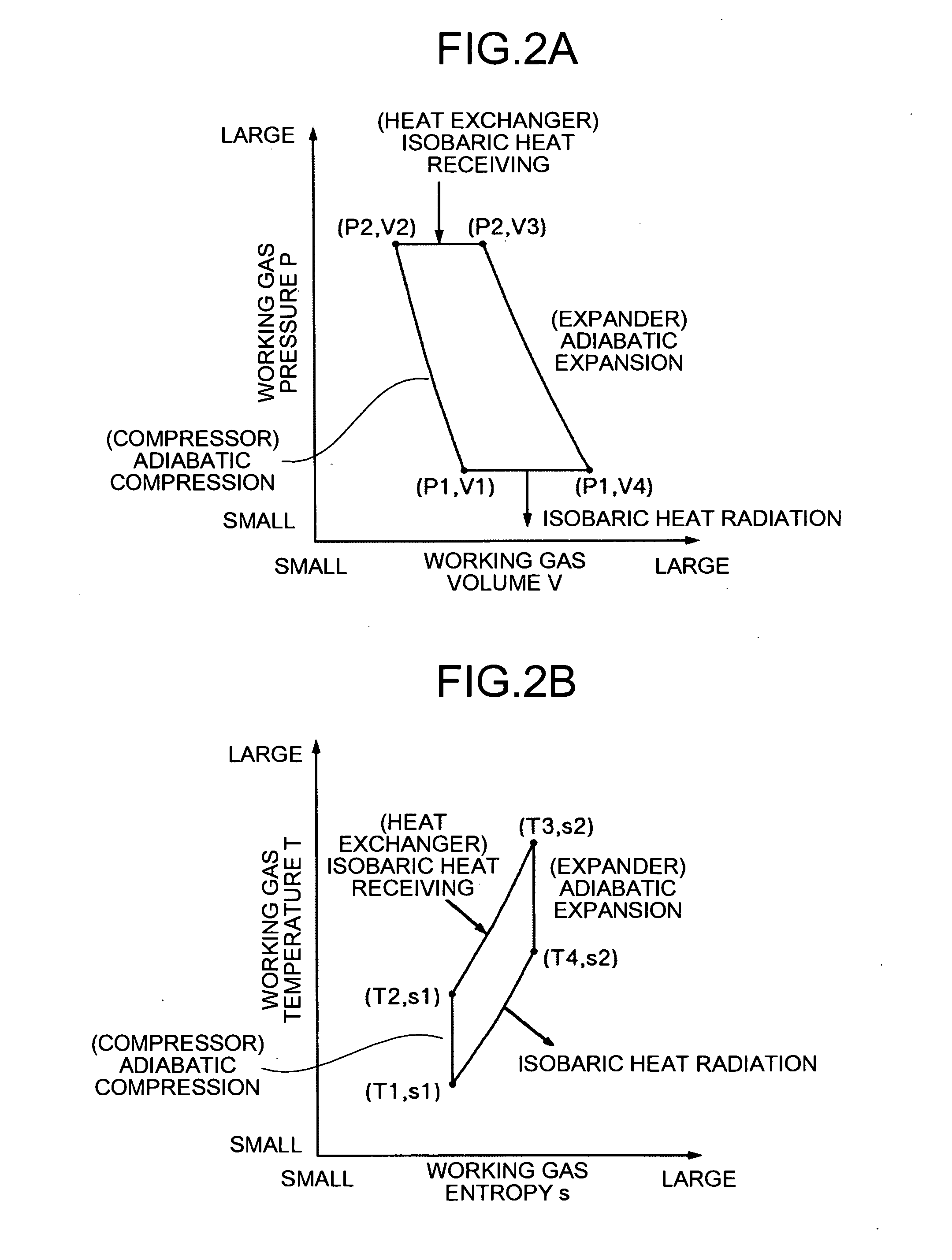
[0032] The heat energy recovery apparatus of the first embodiment is a Brayton cycle engine in which working fluid is processed using heat of high temperature fluid as follows: adiabatic compression→isobaric heat receiving→adiabatic expansion→isobaric heat radiation, thereby obtaining driving force. As shown in FIG. 1, the heat energy recovery apparatus includes a compressor 10 which adiabatically compresses suck-in working fluid, a heat exchanger 20 which makes the working fluid adiabatically compressed by the compressor 10 absorb heat of high temperature fluid under isobaric pressure, and an expander 30 which makes the working fluid isobarically heat-received by the heat exchanger 20 expand adiabatically.

[0033] Here, exhaust gas discharged from an internal combustion engine 60 shown in FIG. 1 is used as the high temperature fluid and exhaust heat of the exhaust ga...

second embodiment

[0058] A heat energy recovery apparatus according to the present invention will be described with reference to FIG. 3 and FIG. 4. In addition, here, also as the heat energy recovery apparatus, an exhaust heat recovery apparatus which recovers exhaust heat of an internal combustion engine 60 will be explained with an example.

[0059] The exhaust heat recovery apparatus of the second embodiment is one in which the heat exchanger 20 is replaced with a heat exchanger 120 shown in FIG. 3, in the heat energy recovery apparatus of the aforementioned first embodiment.

[0060] Specifically, the heat exchanger 120 of the second embodiment includes a first flow path 121 in which high temperature fluid (exhaust gas) flown in from the exhaust flow path 61 of the internal combustion engine 60 flows and a second flow path 122 in which working gas adiabatically compressed by the compressor 10 flows.

[0061] The heat exchanger 120, as shown in FIG. 3 and FIG. 4, includes a cylindrical first interconnect...

third embodiment

[0071] A heat energy recovery apparatus according to the present invention will be described with reference to FIG. 5. In addition, here, also as the heat energy recovery apparatus, an exhaust heat recovery apparatus which recovers exhaust heat of an internal combustion engine 60 will be explained with an example.

[0072] Here, exhaust gas having temperature higher than that of a heat exchanger 120 flows into an exhaust flow path 61 of the internal combustion engine 60 side and thermal expansion occurs is such a portion. Therefore, for example, in the exhaust heat recovery apparatus of the aforementioned second embodiment, when a relative position relationship between the exhaust flow path 61 and the expander 30 of the exhaust heat recovery apparatus and the working gas supply pipe 34 thereof is fixed, tensile stress and / or compressive stress occur in the working gas supply pipe 34 of the expander 30 with the thermal expansion of the exhaust flow path 61 of the internal combustion eng...


PUM


Abstract

A heat energy recovery apparatus includes a compressor; a heat exchanger; an expander; a working gas exhaust pipe which leads the working gas compressed by the compressor to the heat exchanger; a working gas exhaust path generally parallel to a direction of the thermal expansion of the heat exchanger; an extending unit extensible in the same direction as that of the thermal expansion when the heat exchanger expands thermally and tensile stress occurs in the working gas exhaust path with the thermal expansion of the heat exchanger; and a shrinking unit shrinkable in the same direction as that of the thermal expansion when the heat exchanger expands thermally and compressive stress occurs in the working gas exhaust path with the thermal expansion of the heat exchanger.

Description

BACKGROUND OF THE INVENTION [0001] 1. Field of the Invention [0002] The present invention relates to a heat energy recovery apparatus for converting thermal energy in which heat is absorbed by a heat exchanger to mechanical energy. [0003] 2. Description of the Related Art [0004] Conventionally, there exists a heat cycle engine that converts thermal energy to mechanical energy. [0005] For example, as this kind of a heat cycle engine, there is a Brayton cycle engine which includes a compressor which has a piston for adiabatically compressing sucked-in working fluid (working gas), a heat exchanger (heat source) which makes the working gas adiabatically compressed by the compressor absorb heat of high temperature fluid under isobaric pressure, and an expander which makes a piston move under pressure by adiabatic expansion of the working gas isobarically heat-received by the heat exchanger; and which takes out output from a crankshaft using the expansion force, as disclosed in Japanese P...

Claims


Application Information

Patent Timeline
Patent Type & Authority Applications(United States)
IPC IPC(8): F02G1/04F01B29/10
CPCF02B41/00F02G1/02Y02T10/166F02G2280/60F02G5/02Y02T10/12
Inventor MITANI, SHINICHISAWADA, DAISAKU
Owner TOYOTA JIDOSHA KK
Learn More