Ultrasonic inspection method and ultrasonic inspection equipment

a technology of ultrasonic and inspection equipment, applied in ultrasonic/sonic/infrasonic diagnostics, instruments, specific gravity measurements, etc., can solve the problems of reducing the resolution of space, limiting the transmission/receiving period of ultrasonic waves, and completing measurement necessities a tremendous amount of time, so as to reduce random noise, enhance the s/n ratio of the resultant inspection image, and improve the effect of measurement efficiency

Active Publication Date: 2006-10-05
HITACHI LTD
View PDF8 Cites 55 Cited by
  • Summary
  • Abstract
  • Description
  • Claims
  • Application Information

AI Technical Summary

Benefits of technology

[0029] According to the present invention, the inspection of the inside of an inspection target is performed in a manner of changing the incident angles of the ultrasonic waves oscillated from the array-probe ultrasonic sensor. Also, the set-up position of the array-probe ultrasonic sensor is sequentially displaced. Moreover, the inspection images acquired at the respective inspection positions are visualized by adding or averaging the inspection images while shifting the images by the displacement quantity of the array-probe ultrasonic sensor. This allows acquisition of the convergence effect on the ultrasonic waves without setting the focal depths in particular detail. Accordingly, it becomes possible to acquire the high-resolution inspection images at almost all the depth positions. This permits implementation of the high-accuracy nondestructive inspection. Furthermore, the addition or averaging of the inspection images makes it possible to reduce the random noises, thereby allowing an enhancement in the S / N ratio of the resultant inspection image.
[0030] Also, according to the present invention, there are provided the array-probe ultrasonic sensor including the plurality of piezoelectric vibration elements, the pulser for transmitting the transmission signal with each piezoelectric vibration element of the array-probe ultrasonic sensor, and the receiver for transmitting / receiving the reception signal therewith, the delay control unit for exercising the time control by setting the delay time to the transmission signal and the reception signal, the delay time being made variable on each piezoelectric-vibration-element basis, the data storage unit for storing the ultrasonic waveforms transmitted and received at the array-probe ultrasonic sensor, the sensor displacement unit for scanning the array-probe ultrasonic sensor, the scan control unit for controlling the scan, the displacement-quantity detection unit for measuring the displacement quantity of the array-probe ultrasonic sensor, the image-processing unit for generating the plurality of inspection images from the ultrasonic waveforms stored, and adding or averaging the plurality of inspection images by shifting the images by the amount of the displacement quantity measured in the displacement-quantity detection unit of the array-probe ultrasonic sensor, and the display unit for displaying the inspection images and the inspection image acquired from the addition. This makes it possible to acquire the convergence effect on the ultrasonic waves without setting the focal depths in particular detail. Accordingly, it has become possible to implement the high-resolution inspection images, thereby allowing implementation of the high-accuracy nondestructive inspection.
[0031] Also, as a result, according to the present invention, there is provided the processing-contents switch unit for switching between the inspection methods such as the linear scan scheme and the sectorial scan scheme, i.e., the conventional inspection methods using the array-probe ultrasonic sensor, and the above-described inspection image processing method. This allows implementation of the operations as well which are basically the same as those in the conventional inspection methods.
[0032] Similarly, according to the present invention, in the inspection using the array-probe ultrasonic sensor, it becomes possible to acquire the convergence effect on the ultrasonic waves without setting the focal depths in particular detail. As a result, it becomes possible to acquire the high-resolution inspection images at almost all the depth positions even if the positions are distant from the sensor.
[0033] Furthermore, according to the present invention, it becomes possible to acquire the high-resolution and high-S / N-ratio inspection images even if, unlike the synthetic aperture method, the high-level computational operation is not performed with a long time spent. This allows the inspection results to be speedily evaluated even on an actual site of the inspection.
[0034] According to the present invention, it becomes possible to acquire the convergence effect on the ultrasonic waves without setting the focal depths in particular detail. This allows the high-resolution and high-S / N-ratio inspection image to be speedily acquired with ease-of-operability. As a result, it becomes possible to carry out the high-accuracy and excellent-reliability nondestructive inspection.

Problems solved by technology

This, eventually, has resulted in a problem that the space resolution will be lowered at a depth position at which the focusing is not achieved.
At this time, however, there exists a limit to the transmission / reception repetition period of the ultrasonic wave.
This has resulted in a problem that completing the measurement necessities a tremendous amount of time, which is not realistic.
Moreover, in this phased array method, the evaluation of a defect needs to be performed by watching an enormous number of inspection images which are divided in correspondence with the focal depths.
This has resulted in a problem that evaluating these inspection images becomes an extremely complicated and troublesome task.
On account of this, if attenuation of the ultrasonic wave due to the diffusion is large, and if the inspection target is thick and the propagation distance of the ultrasonic wave is long, the intensity of the ultrasonic wave at a point farther distant from the ultrasonic sensor becomes significantly weak.
This has resulted in a problem that the reception of the reflected ultrasonic wave becomes difficult, and that the reflected ultrasonic wave becomes highly likely to undergo influences by various types of noises the typical of which is electric noise, and that the S / N ratio is lowered.

Method used


Image

  • Ultrasonic inspection method and ultrasonic inspection equipment
  • Ultrasonic inspection method and ultrasonic inspection equipment
  • Ultrasonic inspection method and ultrasonic inspection equipment

Examples


second embodiment

[0077] Next, FIG. 6 illustrates the processing according to the present invention. This processing is about the case where the range of the inspection images which become the inspection area is set over the entire scan area by the array-probe ultrasonic sensor 101, and the case where the inspection-image size is also inspected in the determined state. Namely, using the displacement quantity of the array-probe ultrasonic sensor 101 detected by the displacement-quantity detection unit 106, the inspection image is acquired by shifting, by the pixel number equivalent to the displacement quantity of the array-probe ultrasonic sensor 101, and superimposing the inspection images acquired at the respective inspection positions within the range of the inspection images set in advance.

[0078] Accordingly, in this second embodiment, at all the positions from the inspection start position (1) to the inspection termination position (n), the inspection images have become the same area. As a result...

first embodiment

[0079] The characteristic of this processed image becomes basically the same as the case in the Namely, with respect to the defect corner echo 103K and the defect tip echo 103J, only the signal at a real defect position selectively remains by the superimposition of the ultrasonic waves entering from the various angles.

[0080] Next, referring to FIG. 7, the explanation will be given below regarding an application example of the present methodology. At first, in FIG. 7, a test body 700, i.e., an object which becomes the test body, is used as the inspection target. In this test body 700, a plurality of holes referred to as “drill holes” here are artificially provided at different-depth (i.e., thickness direction) positions in a steel plate material by using a hole-boring tool. These drill holes are bored so as to be regarded and utilized as defects. FIG. 7 illustrates a plurality of inspection images, and a processed image acquired by adding the plurality of inspection images. As the d...

third embodiment

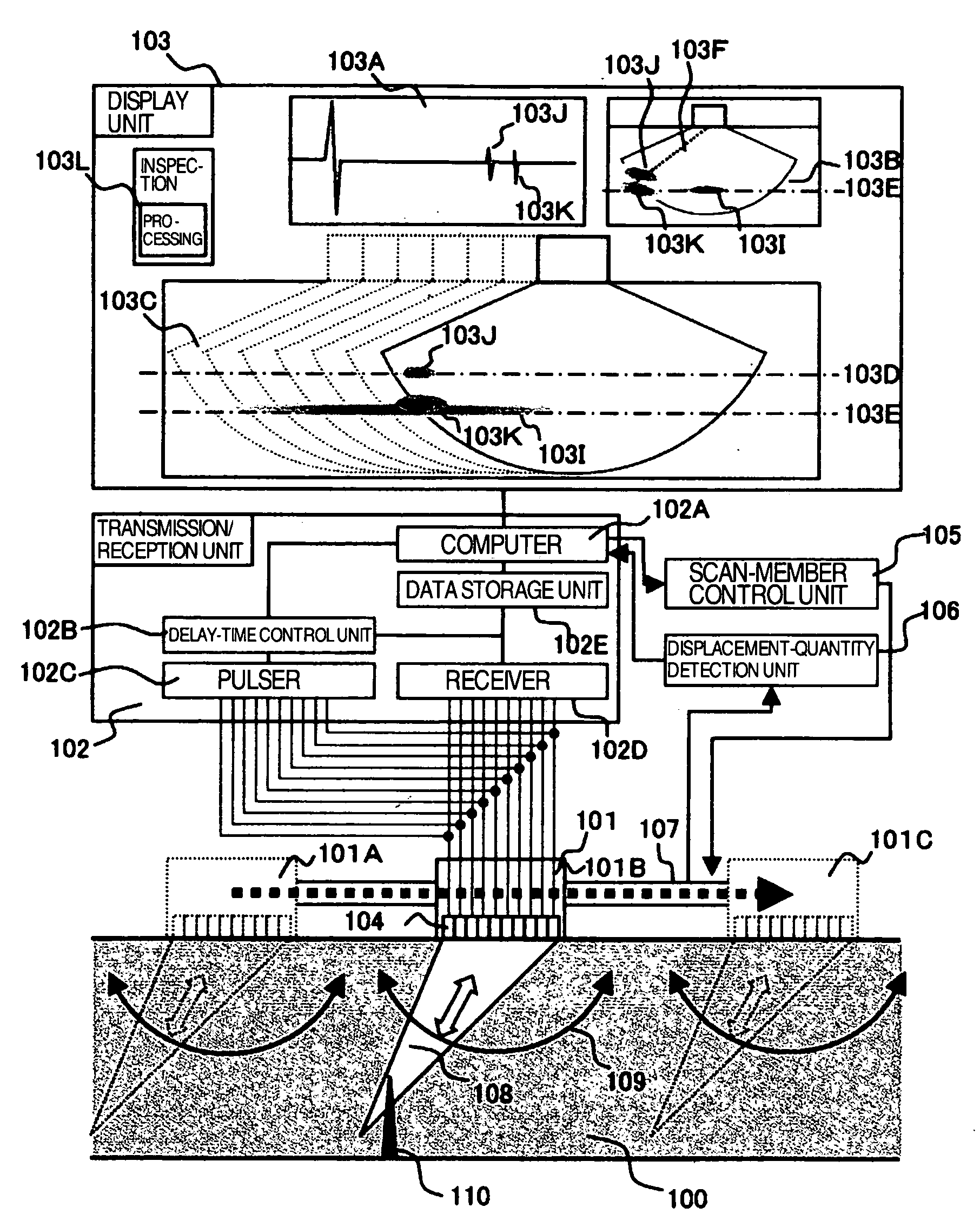
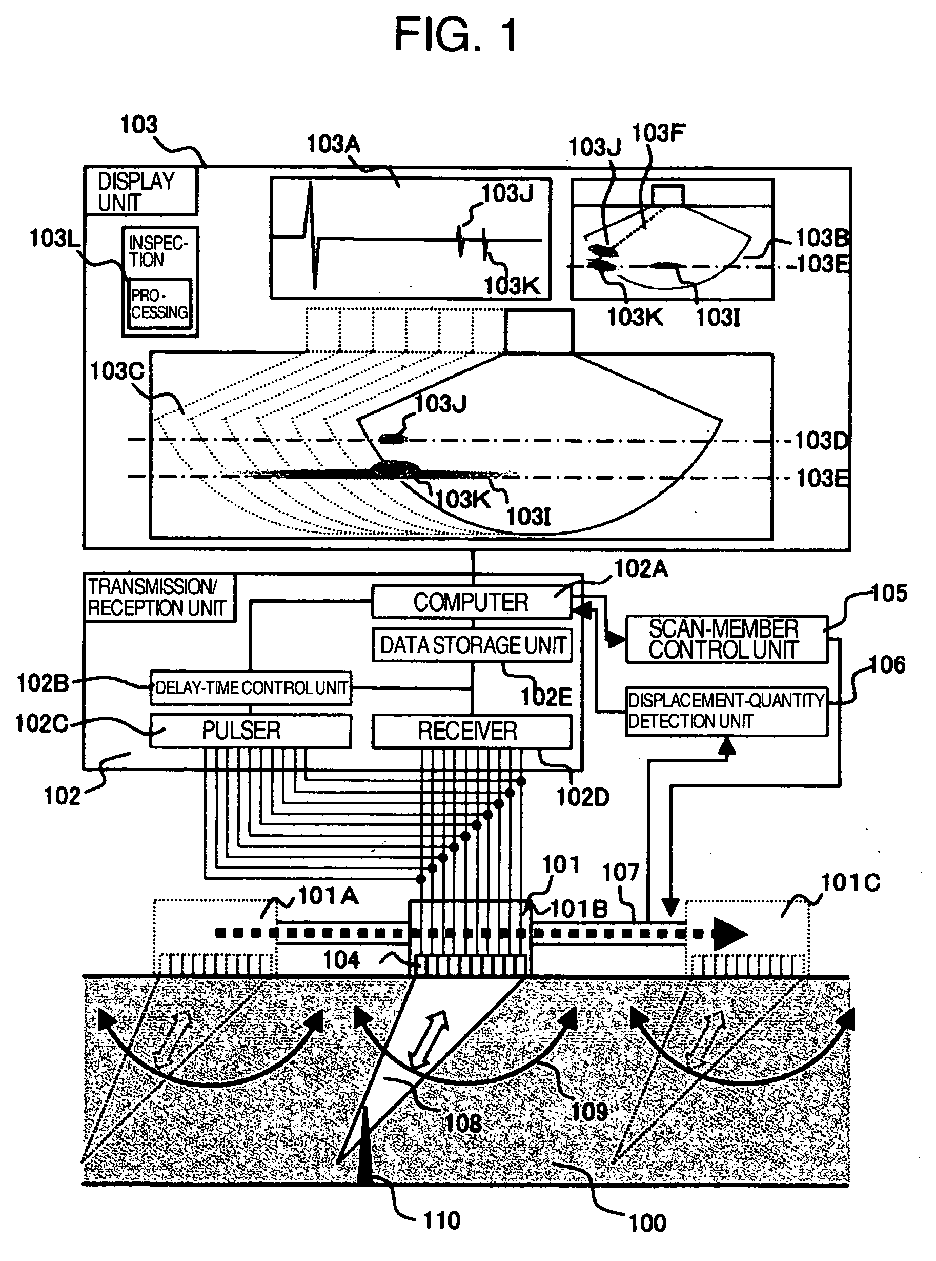
[0098] Furthermore, in this third embodiment, taking advantage of the array-probe ultrasonic sensor 1000 of this kind allows implementation of the following operation: Namely, the displacement (i.e. scan) of the transmission position and reception position of the ultrasonic wave by the array-probe ultrasonic sensor, which is needed from the inspection start to the inspection termination, can be acquired by electrically switching the piezoelectric vibration elements 104 inside the array-probe ultrasonic sensor 1000. Accordingly, here, the sensor displacement member 107 in the embodiment in FIG. 1 is unnecessary. In accompaniment therewith, the scan-member control unit 105 and the displacement-quantity detection unit 106 are also unnecessary. The other configurations, however, are the same as those in the embodiment in FIG. 1.

[0099] The ultrasonic-wave scan method based on the electrical switching for the piezoelectric vibration elements 104 is referred to as “electronic scan scheme”....


PUM

PropertyMeasurementUnit
angleaaaaaaaaaa
angleaaaaaaaaaa
angleaaaaaaaaaa

Abstract

In the ultrasonic inspection method and equipment, a high-resolution and high-S/N-ratio inspection image can be speedily acquired with ease-of-operability. Inspection of the inside of the inspection target is performed by changing incident angle of the ultrasonic wave oscillated from the array-probe ultrasonic sensor. Then, while performing the inspection, the array-probe ultrasonic sensor is sequentially displaced from the position to the position via the position by using the displacement member. This displacement allows acquisition of inspection images on each position basis. Finally, the inspection images thus acquired are visualized as a processed image by adding or averaging the inspection images by shifting the images by displacement quantity of the array-probe ultrasonic sensor.

Description

BACKGROUND OF THE INVENTION [0001] 1. Field of the Invention [0002] The present invention relates to an ultrasonic inspection method, i.e., one type of nondestructive inspection techniques. More particularly, it relates to the ultrasonic inspection method and equipment therefor using an array-probe ultrasonic sensor. [0003] 2. Description of the Related Art [0004] In the ultrasonic inspection methods intended for dealing with various types of structural materials as the inspection targets, from conventionally, detecting a defect is performed as follows: Namely, an ultrasonic sensor including a single element is used for transmission and reception of ultrasonic wave. Then, an ultrasonic signal reflected by a defect or the like inside an inspection target is detected. Finally, the defect is detected based on the propagation time and position of the ultrasonic sensor. [0005] At this time, the ultrasonic sensor is caused to displace, then determining positions at which the reflected wav...

Claims


Application Information

Patent Timeline
Patent Type & Authority Applications(United States)
IPC IPC(8): G01N29/04G01N29/00
CPCG01N29/043G01N29/0609G01N29/069G01N2291/106G01N29/449G01N2291/044G01N29/262
Inventor BABA, ATSUSHIKONO, NAOYUKIMUSHA, YOSHINORI
Owner HITACHI LTD
Why Eureka
Try Eureka