Magnetic field forming device, ferrite magnet producing method, and mold

Inactive Publication Date: 2006-10-05
TDK CORPARATION
View PDF10 Cites 10 Cited by
  • Summary
  • Abstract
  • Description
  • Claims
  • Application Information

AI Technical Summary

Benefits of technology

[0032] The present invention heats a slurry to be injected into a die by controlling temperature of the die to reduce viscosity of the dispersion medium in the slurry. This allows the slurry to keep its dehydration properties at a high level during the molding process in a magnetic field, and to be efficiently dehydrated even

Problems solved by technology

The wet magnetic field molding involves a problem of decreased production yield resulting from cracking or the like of the molded body, unless the slurry is dehydrated enough

Method used


Image

  • Magnetic field forming device, ferrite magnet producing method, and mold
  • Magnetic field forming device, ferrite magnet producing method, and mold
  • Magnetic field forming device, ferrite magnet producing method, and mold

Examples


Example

Example 1

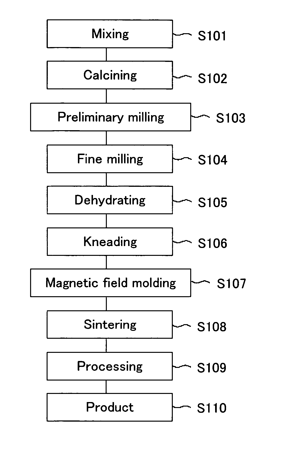
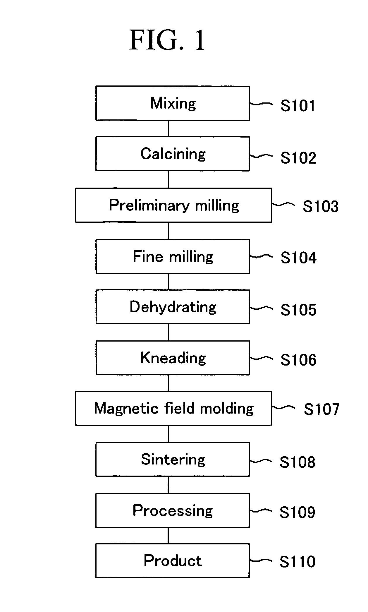
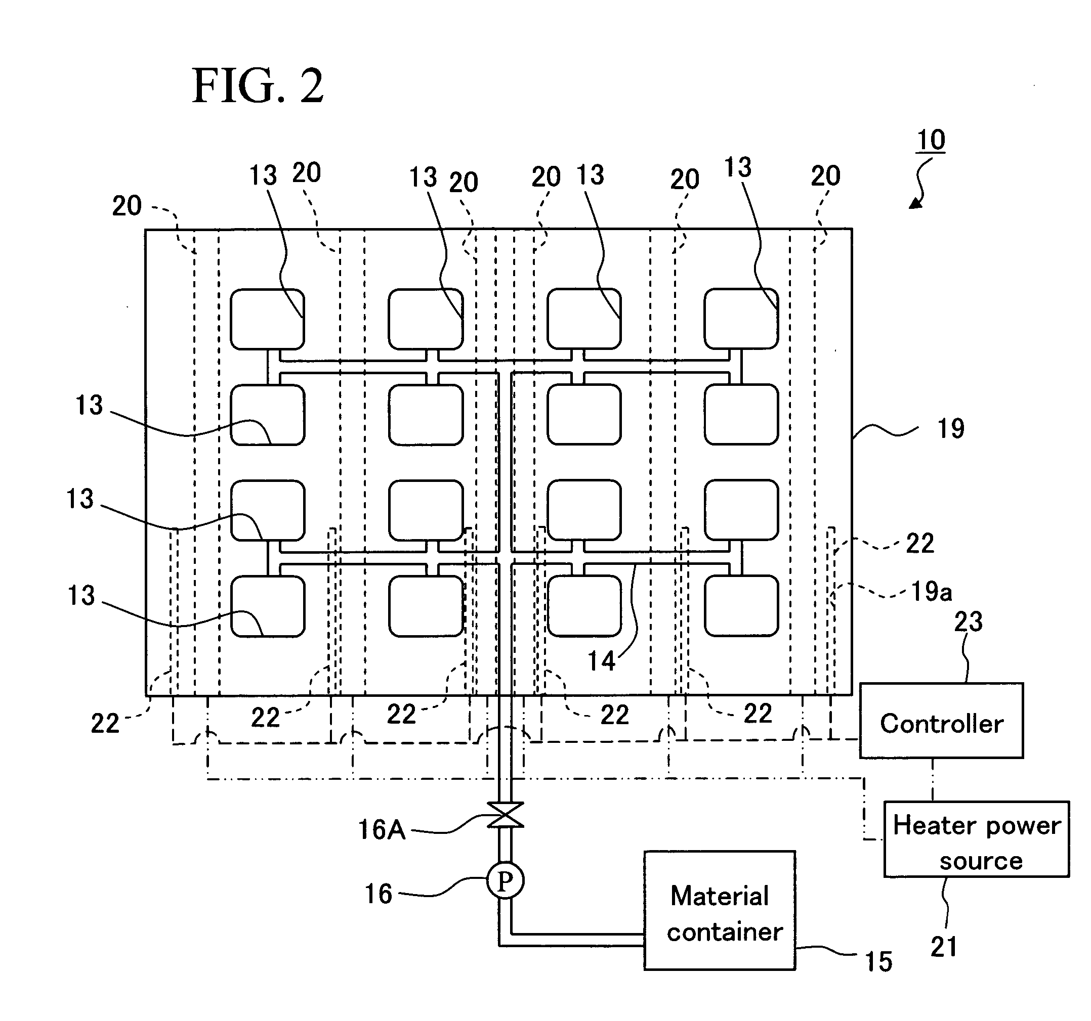
[0087] The slurry was molded in a magnetic field using the magnetic field molding device 10, illustrated in FIG. 2, into a molded body and the obtained molded body was sintered into a ferrite magnet, where temperature T1 of the mortar-shaped die 19 was kept at 50° C. by the heater member 20.

Example

Example 2

[0088] The slurry was molded in a magnetic field using the magnetic field molding device 10 into a molded body and the obtained molded body was sintered into a ferrite magnet, where temperature T1 of the mortar-shaped die 19 was kept at 60° C. by the heater member 20.

Example

Example 3

[0089] The slurry was molded in a magnetic field using the magnetic field molding device 10 into a molded body and the obtained molded body was sintered into a ferrite magnet, where temperature T1 of the mortar-shaped die 19 was kept at 100° C. by the heater member 20.


PUM

PropertyMeasurementUnit
Temperatureaaaaaaaaaa

Abstract

The objects of the present invention are to provide a magnetic field molding device, and method for producing a ferrite magnet, or the like, capable of improving yield in a production line and stabilizing product quality, and method for producing a ferrite magnet.
In molding in a magnetic field, the mortar-shaped die 19 provided with a plurality of the cavities 13 is heated by the heater member 20 at a given temperature level, under the control of the controller 23. The temperature level is preferably controlled by the controller 23 at 40° C. or higher as mortar-shaped die 19 temperature T1, sensed by the sensor 22. A molding slurry can be kept at a high temperature level in the cavities 13 by heating the mortar-shaped die 19, and can have high dehydration properties and improve product yield.

Description

TECHNICAL FIELD [0001] The present invention relates to a magnetic field molding device, method for producing a ferrite magnet, and die which can be used for them. BACKGROUND ART [0002] Ferrite (sintered) magnets as prevailing magnets are produced by a series of steps of calcining a raw material mixture with a given composition into a ferrite state, milling the resulting calcined body into a fine ferrite powder of submicron size, compression-molding the powder using a die in a magnetic field (hereinafter referred to as magnetic field molding), and sintering the molded body into a ferrite magnet. [0003] The processes for magnetic field molding fall into two general categories; dry process wherein the powder is molded as a dried material and wet process wherein the powder is molded as a slurry. [0004] The wet magnetic field molding involves a problem of decreased production yield resulting from cracking or the like of the molded body, unless the slurry is dehydrated enough to remove i...

Claims


Application Information

Patent Timeline
IPC IPC(8): H01F1/03B22F1/00B22D41/01B28B3/02B30B11/00B30B11/02C04B35/622H01F1/113H01F41/02
CPCC04B35/622H01F41/0266H01F1/113
Inventor MASUZAWA, KIYOYUKIKURITA, HIDEOOHTSUKA, MASAYUKINAGATSUKA, YASUHIROTAGUCHI, HITOSHI
Owner TDK CORPARATION
Why Eureka
Try Eureka