Method for temperature measurement in a household appliance

a technology for household appliances and temperature measurement, applied in the direction of temperature measurement in household appliances, domestic stoves or ranges, and converting sensor output using wave/particle radiation, etc., can solve the problem that lc resonant circuits are generally not suitable for use, and achieve the effect of reducing the complexity of circuitry, simplifying further processing, and improving the accuracy of temperature measuremen

Active Publication Date: 2006-10-05
MIELE & CIE KG
View PDF3 Cites 62 Cited by
  • Summary
  • Abstract
  • Description
  • Claims
  • Application Information

AI Technical Summary

Benefits of technology

[0005] It is, therefore, an object of the present invention to provide a method for temperature measurement in a household appliance, which is less complex in terms of circuitry and less prone to failure and which is also suitable for use at elevated temperatures.

Problems solved by technology

The known system has the disadvantage that LC resonant circuits are generally not suitable for use at high temperatures, such as around 250° C.

Method used


Image

  • Method for temperature measurement in a household appliance
  • Method for temperature measurement in a household appliance
  • Method for temperature measurement in a household appliance

Examples


Embodiment Construction

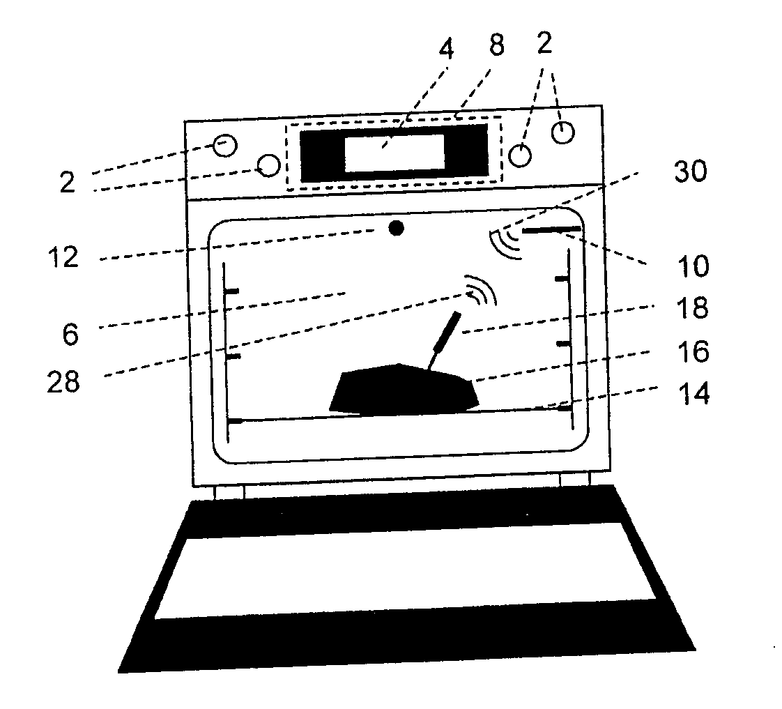
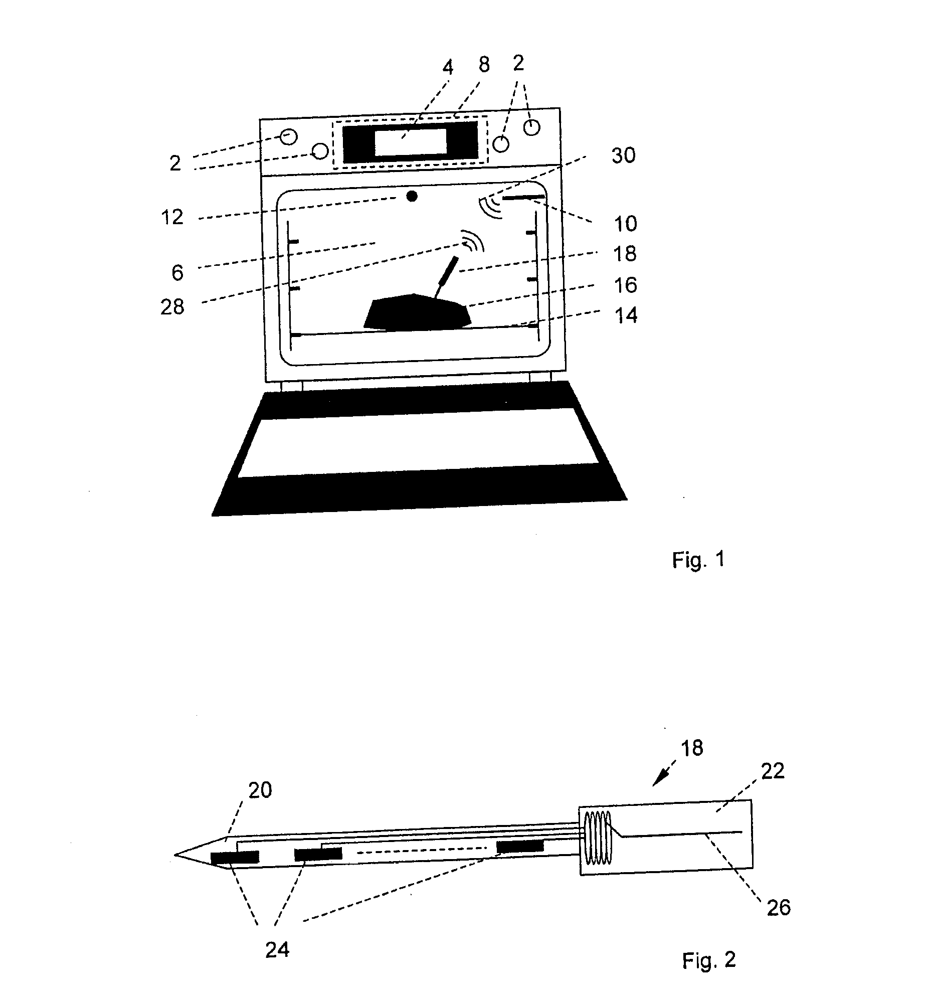
[0031]FIG. 1 shows a household appliance in the form of a baking oven in which the method according to the present invention is used. The baking oven has control elements 2 and a display device 4, an oven chamber 6 and an electrical processing unit 8 symbolized by a dashed line. Control elements 2 and display device 4 are connected in signal communication to electrical processing unit 8 in a manner known to those skilled in the art. The same applies to a cooking chamber antenna 10 and an additional temperature measuring probe 12, which is also disposed in oven chamber 6. Here, the additional temperature measuring probe 12 includes a PT 1000 temperature sensor. However, it is, in principle, also possible to use other types of temperature sensors that have a constant correlation between the input and the output over their lifetimes. It is also possible to use a plurality of additional temperature measuring probes 12 instead of only one additional temperature measuring probe 12, which ...


PUM


Abstract

A method for temperature measurement in a household appliance includes generating a high-frequency electromagnetic excitation wave of a predefined transmit frequency. The transmit frequency is selected from a frequency band including temperature-dependent resonant frequencies that occur in a surface wave device incorporated in a temperature measuring probe and which respectively correspond to temperatures expected at the temperature measuring probe during operation of the household appliance. During a first phase, the excitation wave is wirelessly transmitting to the surface wave device. During a second phase following the first phase, an electromagnetic response wave generated by the excitation wave in the surface wave device is wirelessly transmitting to a processing unit. Signal levels of response signals generated from response waves of different transmit frequencies are measured and compared to determine the current temperature of the surface wave device based on the transmit frequency associated with the highest signal level.

Description

[0001] Priority is claimed to German patent application DE 10 2005 015 028.4, filed Mar. 31, 2005, the entire subject matter of which is hereby incorporated by reference herein. [0002] The present invention relates to a method for temperature measurement in a household appliance. BACKGROUND [0003] A method for temperature measurement in a household appliance is described, for example, in German Patent DE 29 35 282 C2. In the known method, a processing unit of the household appliance generates a high-frequency electromagnetic excitation wave. The pre-defined transmit frequency is selected from a frequency band containing the temperature-dependent resonant frequencies that occur in an LC resonant circuit incorporated in a temperature measuring probe and which correspond to the temperatures expected at the temperature measuring probe during operation of the household appliance. During a first phase, the excitation wave is wirelessly transmitted to the LC resonant circuit of the tempera...

Claims


Application Information

Patent Timeline
Patent Type & Authority Applications(United States)
IPC IPC(8): H05B1/02H05B6/12
CPCG01D5/48G01K1/024G01K11/265H04Q2209/84H04Q9/00H04Q2209/40G01K2207/06G01K1/026F24C7/085
Inventor BEIER, DOMINICMEIERFRANKENFELD, WENZEL
Owner MIELE & CIE KG
Why Eureka
Try Eureka