Plasma processing method and apparatus, and autorunning program for variable matching unit

a processing method and variable matching technology, applied in the field of plasma processing technology, can solve the problems of difficult ignition of plasma and affecting the process, and achieve the effects of improving ensuring the reliability of auto-matching function, and facilitating plasma ignition

Active Publication Date: 2006-10-05
TOKYO ELECTRON LTD
View PDF5 Cites 55 Cited by
  • Summary
  • Abstract
  • Description
  • Claims
  • Application Information

AI Technical Summary

Benefits of technology

[0006] It is, therefore, an object of the present invention to provide a plasma processing method and apparatus and an autorunning program for a matching unit capable of readily improving the plasma ignition with no particular selection or change of processing conditions while influencing none of the processes.
[0007] Another object of the present invention is to provide a plasma processing apparatus and method capable of improving auto-matching reliability for automatically matching a load impedance to an impedance of the radio frequency power source side during the plasma processing.
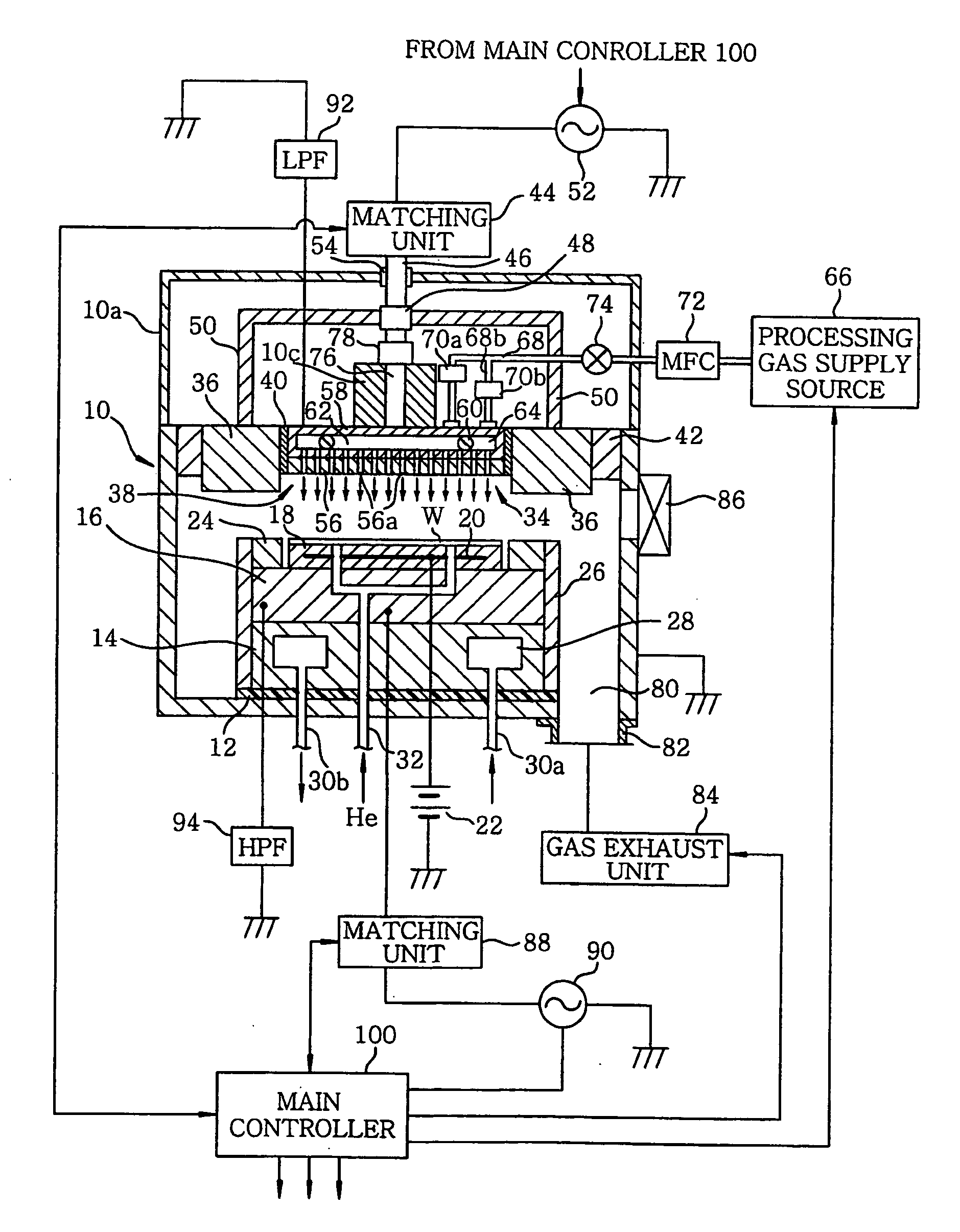
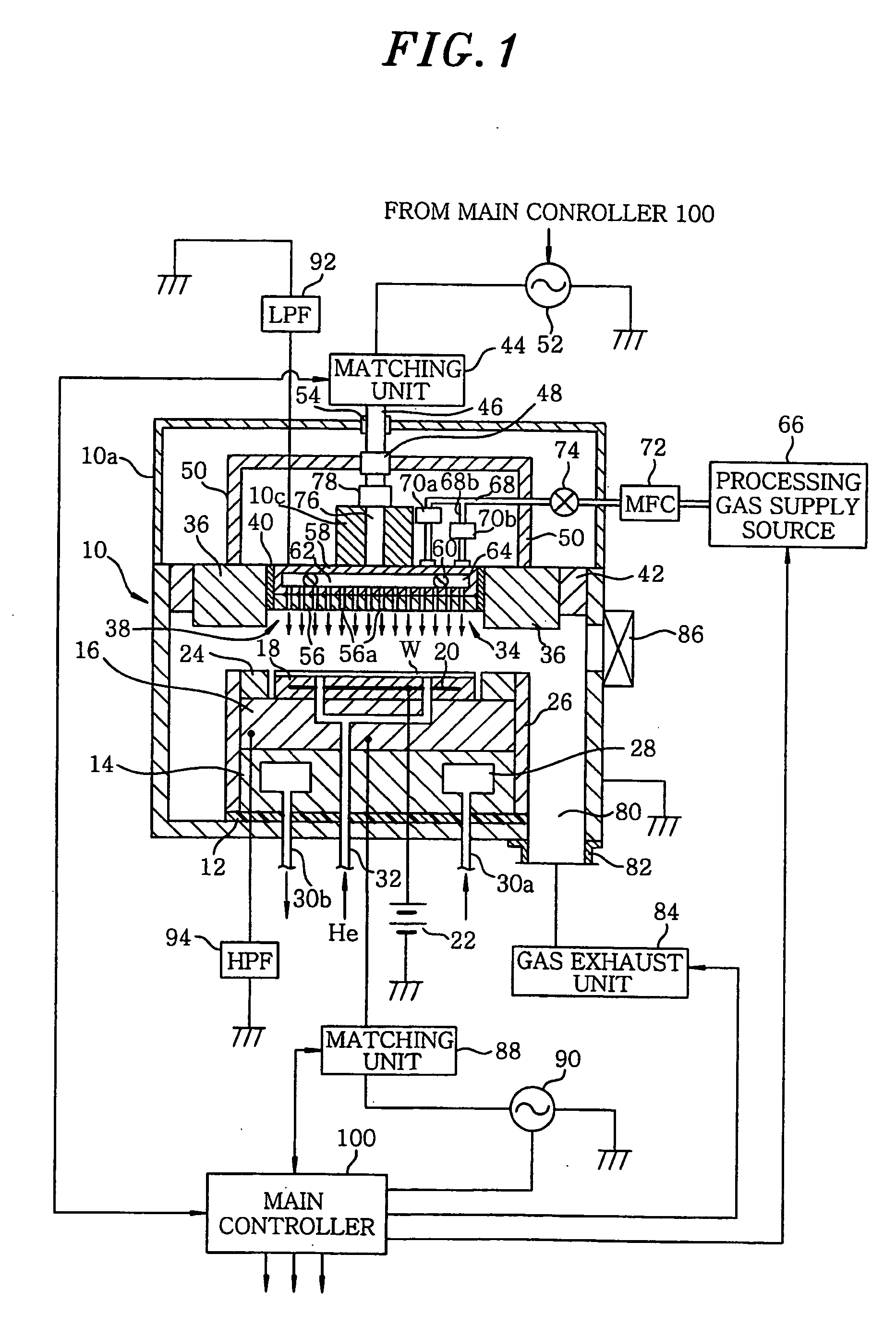
[0010] With the above-described configuration, when the first radio frequency power from the first radio frequency power source is applied to the first radio frequency electrode, a maximum peak value of voltage or a value close to it, which is available in a variable range of impedance of the first variable matching unit, is obtained at the first radio frequency electrode, so that the electric discharge of the processing gas is facilitated at a maximum to generate a plasma of the processing gas. Further, after the ignition of the plasma, the variable matching unit is converted from the fixed impedance (the first impedance) to a variable impedance, the impedance matching is carried out between the first radio frequency power supply and the load even tough the impedance of the plasma is varied, thereby maintaining the plasma process stable.
[0012] Further, in the plasma processing method or apparatus, it is preferable that the first radio frequency electrode and a second radio frequency electrode are disposed in parallel with a gap therebetween in the chamber, a second radio frequency power of a second frequency is applied from a second radio frequency power supply to the second radio frequency electrode via a second matching unit. In this case, the application of the second radio frequency power to the second radio frequency electrode is initiated after the plasma is ignited in the chamber. It is preferable to initiate the application of the second radio frequency power under a second impedance where a peak value of a radio frequency voltage obtained at the second radio frequency electrode becomes a minimum value or a value close to it among variable impedances in the second variable matching unit; and to variably control an impedance of the second variable matching unit such that the load impedance is matched to an impedance at the side of the second radio frequency power supply after a predetermined time period from the time the application of the second radio frequency power is initiated. In this way, the influence of the second radio frequency power on the plasma generated by the first radio frequency power can be suppressed at a minimum.
[0017] With the above-described method and apparatus, even if there occurs a measuring error in the load impedance measuring circuit or the wave distortion of the radio frequency during the actual process is large, the auto-matching is operated so as to make the power of the reflected wave minimum without depending on the seeming measured value of the load impedance, so that the reliability of the auto-matching function is guaranteed.
[0018] In accordance with the plasma processing method and apparatus and the matching unit autorunning program of the present invention, it is possible to readily improve the plasma ignition without requiring to set or change special processing conditions while influencing none of the processes. Further, it is possible to improve the auto-matching reliability for automatically matching a load impedance to an impedance of the radio frequency power source side during a plasma processing.

Problems solved by technology

However, when the gas pressure in the chamber is low, the plasma is difficult to get ignited.
However, such a method is cumbersome in that an optimal initial pressure for the plasma ignition should be set for every process, and further it is not assured that the plasma will be securely ignited under an initial pressure slightly higher than the required level.
Meanwhile, if the initial pressure is much higher than the required level, the transition of the pressure after the plasma ignition may affect the process.

Method used


Image

  • Plasma processing method and apparatus, and autorunning program for variable matching unit
  • Plasma processing method and apparatus, and autorunning program for variable matching unit
  • Plasma processing method and apparatus, and autorunning program for variable matching unit

Examples


first example

[0055]FIG. 3 shows a configuration of a radio frequency power supply system in accordance with a first example, which is applicable to the aforementioned plasma etching apparatus. The upper matching unit 44 is an impedance-variable matching unit, and includes a matching circuit 102 containing at least one variable reactance element, a controller 104 for variably controlling impedance positions of the variable reactance element of the matching circuit 102, and an RF sensor 106 for functioning to measure a load impedance Zin containing the matching circuit 102.

[0056] In the illustrated example, the matching circuit 102 is configured in a T-shape to have two variable capacitors C1, C2 and one inductance coil L1, and the controller can variably control the impedance positions of the variable capacitors C1, C2 through respective stepper motors 108, 110. The RF sensor 106 includes a voltage sensor and a current sensor for detecting a n RF voltage and an RF current, respectively, in a tra...

second example

[0079]FIG. 9 shows a configuration of a radio frequency power supply system in accordance with a second example. The second example is different from the first example in terms of the following two points. First, the configuration of the matching circuit 102 is changed from the T-shape to a ladder shape wherein the controller 104 serves to variably control impedance positions of a variable capacitor C3 and a variable inductance coil L2 through the respective stepper motors 108, 110. A capacitor C4 and an inductance coil L4 provided at the downstream side are a fixed capacitor and a fixed inductance coil, respectively. As such, the matching circuit 102 in the matching unit can be configured as an arbitrary variable matching circuit having one or more variable reactance elements. Another feature of this example is that there are provided to the output terminals of the radio frequency power supplies 52, 90 reflected wave measuring circuits 114, 116 for measuring powers of reflected wav...


PUM


Abstract

A plasma processing apparatus includes an upper matching unit 44 which is a variable matching unit whose impedance can be varied, and a main controller 100. The upper matching unit 44 includes a controller 104 for variably controlling the impedance positions of a variable reactance element of a matching circuit 102, a RF sensor for measuring a load impedance including the matching circuit 102, and a VPP measuring circuit 112 for measuring a peak value (peak-to-peak value) of a radio frequency voltage in a waveguide line at the output side of the upper matching unit 44. The main controller 100 executes and controls an autorunning of the matching units 44, 88 for optimizing an off preset of the impedance positions thereof. The plasma can be readily get ignited without requiring to set or change special processing conditions while influencing none of the processes.

Description

FIELD OF THE INVENTION [0001] The present invention relates to a plasma processing technology; and, more particularly, to an improved system for applying a desired radio frequency power to a radio frequency electrode for a plasma generation via a variable matching unit. BACKGROUND OF THE INVENTION [0002] In manufacturing a semiconductor device or a flat panel display (FPD), there has been widely used a plasma processing apparatus for performing, e.g., an etching, a depositing, an oxidizing and a sputtering process by using a plasma. Generally, in the plasma processing apparatus, a radio frequency power supply unit applies a radio frequency power to a radio frequency electrode disposed inside or outside a processing vessel or chamber. The radio frequency power supply unit includes an oscillator or a radio frequency power source for outputting a radio frequency power and a matching unit for matching an impedance at the side of a load (electrode, plasma and chamber) with an impedance a...

Claims


Application Information

Patent Timeline
Patent Type & Authority Applications(United States)
IPC IPC(8): H01J7/24
CPCH01J37/32082H01J37/3299H01J37/32183
Inventor OGAWA, HIROSHI
Owner TOKYO ELECTRON LTD
Why Eureka
Try Eureka