Thermally assisted magnetic recording method

a magnetic recording and magnetic recording technology, applied in combination recording, data recording, instruments, etc., can solve the problems of increasing the density of the recording magnetic field that the magnetic head can apply, reducing the degree of thermal assisted magnetic recording, so as to reduce the ratio of peak temperatures and increase the distance between positions

Inactive Publication Date: 2006-10-05
TOSHIBA STORAGE DEVICE CORP
View PDF10 Cites 13 Cited by
  • Summary
  • Abstract
  • Description
  • Claims
  • Application Information

AI Technical Summary

Benefits of technology

[0020] According to the third aspect of the present invention, preferably, the recording layer may be irradiated with a plurality of laser beams, thus to form a plurality of heated spots. Alternatively, a plurality of heating elements may be disposed so as to face the recording layer and to relatively move with respect thereto, to form a plurality of heated spots. Such methods facilitate properly forming the heated region including a plurality of heated spots aligned in a predetermined direction.
[0021] In the third aspect of the present invention, a plurality of peak temperatures of the heated spots may be controlled, in accordance with the moving speed of the heated region on the recording layer. For example, it is preferable to reduce a ratio of peak temperatures of the subsequent heated spots with respect to the peak temperature of the first heated spot in the moving direction of the heated region, when the heated region moves slower. In the thermally assisted magnetic recording method executed with the magnetic recording medium being rotated, controlling thus a plurality of peak temperatures may be beneficial in leveling off the heating energy amount supplied per unit time to the track during the recording, irrespective of a distance between the track and the rotation center of the medium.
[0022] In the third aspect of the present invention, distance between positions at which the peak temperatures of the plurality of heated spots are attained may be controlled in accordance with the moving speed of the heated region on the recording layer. For example, it is preferable to increase the distance between the positions corresponding to the peak temperature of the plurality of heated spots, when the heated region moves slower. In the thermally assisted magnetic recording method executed with the magnetic recording medium being rotated, controlling thus the distance between positions corresponding to the peak temperature may be beneficial in leveling off the heating energy amount supplied per unit time to the track during the recording, irrespective of a distance between the track and the rotation center of the medium.

Problems solved by technology

The intensity of the recording magnetic field that the magnetic head can apply is, however, subject to a certain limitation from the viewpoint of the structure of the magnetic head as well as the power consumption.
With the conventional thermally assisted magnetic recording method, however, if the heating is so intense when recording information that the temperature is increased over a too extensive region on the recording layer, a cross-write effect may be incurred, for example the record mark excessively spreads over to another track adjacent to the track where the record mark is being formed, thus to erase or degrade the record mark on the adjacent track.
The cross-write effect discourages the attempt of making the track finer, and is hence obviously undesirable from the viewpoint of increasing the recording density of the magnetic disk.
Consequently, the conventional thermally assisted magnetic disk (thermally assisted magnetic recording medium) has a drawback against increasing the recording density.

Method used


Image

  • Thermally assisted magnetic recording method
  • Thermally assisted magnetic recording method
  • Thermally assisted magnetic recording method

Examples


first embodiment

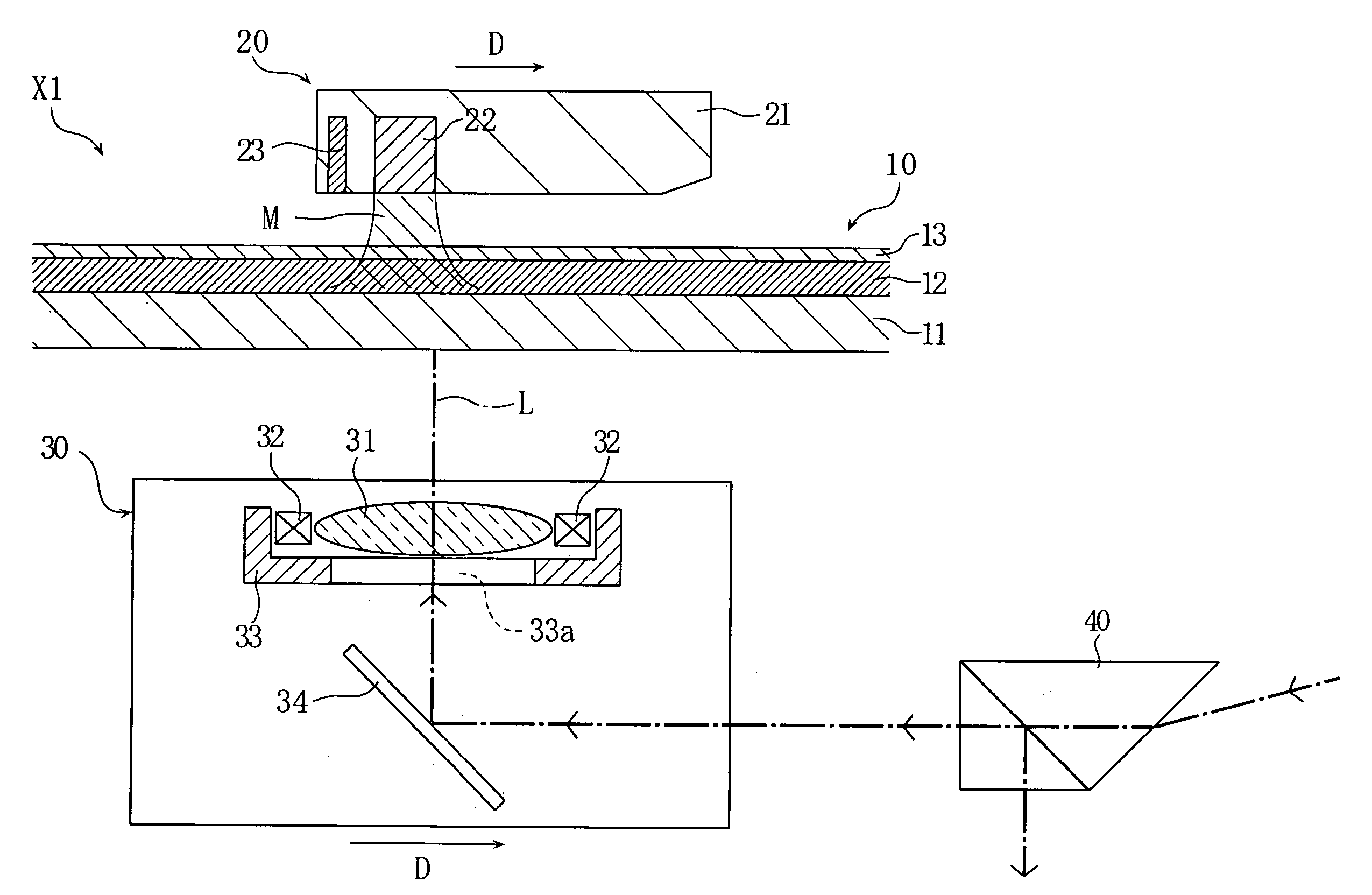
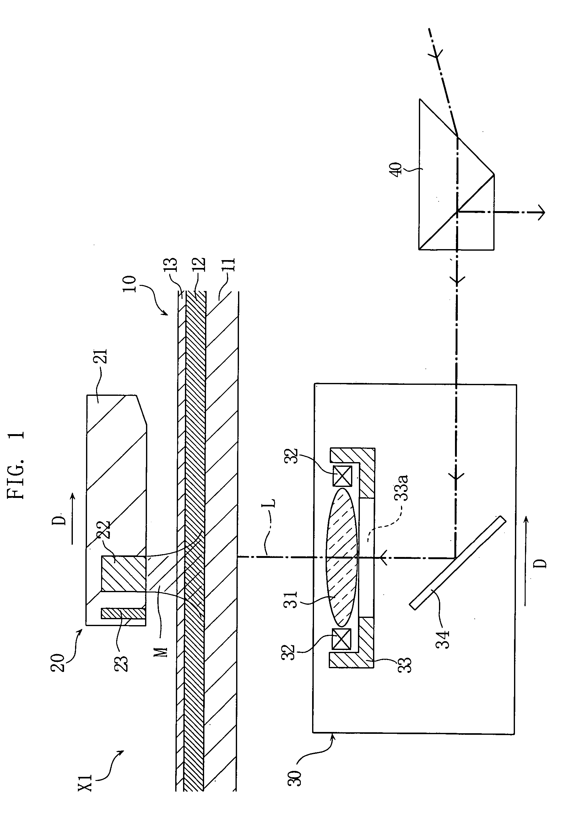
[0036]FIG. 1 is a schematic diagram showing a part of a magnetic disk apparatus X1 for executing a thermally assisted magnetic recording method according to the present invention. The magnetic disk apparatus X1 includes a magnetic disk 10, a magnetic head 20, an optical head 30, and a composite element 40, for recording and reproducing information on and from the magnetic disk 10, by the thermally assisted magnetic recording method.

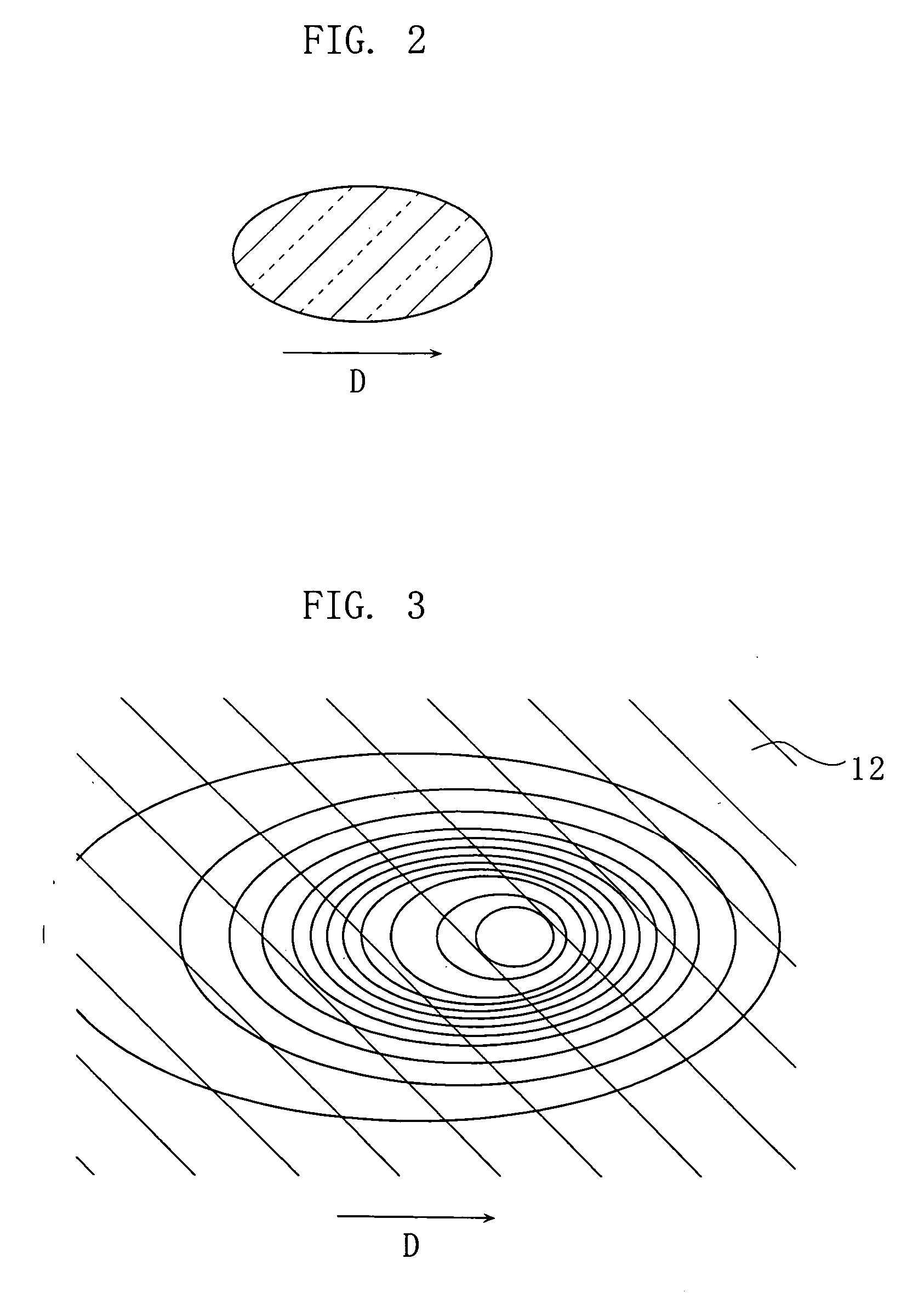
[0037] The magnetic disk 10 has a stacked structure including a disk substrate 11, a recording layer 12, and a cover layer 13, so as to serve as a magnetic recording medium under the thermally assisted magnetic recording system. The disk substrate 11 primarily serves for granting the magnetic disk 10 with sufficient rigidity, and may be constituted of an aluminum alloy, a glass, or a resin. The recording layer 12 is constituted of a vertical magnetized layer or a in-plane magnetized layer, and serves as a recording surface on which information is recorded...

second embodiment

[0046]FIG. 5 is a schematic diagram showing a part of a magnetic disk apparatus X2 for executing a thermally assisted magnetic recording method according to the present invention. The magnetic disk apparatus X2 includes a magnetic disk 10 and a recording / reproducing head 50, for recording and reproducing information on and from the magnetic disk 10, by the thermally assisted magnetic recording method.

[0047] The magnetic disk 10 has a stacked structure including a disk substrate 11, a recording layer 12, and a cover layer 13, so as to serve as a magnetic recording medium under the thermally assisted magnetic recording system. The materials constituting the magnetic disk 10 are the same as those employed in the first embodiment.

[0048] The recording / reproducing head 50 includes a slider body 51, a heating element 52, a recording element 53, and a reproducing element 54, and is disposed so as to face the recording layer 12 of the magnetic disk 10, when the magnetic disk apparatus X2 re...

third embodiment

[0054]FIG. 7 is a schematic diagram showing a part of a magnetic disk apparatus X3 for executing a thermally assisted magnetic recording method according to the present invention. The magnetic disk apparatus X3 includes a magnetic disk 10 and a recording / reproducing head 60, for recording and reproducing information on and from the magnetic disk 10, by the thermally assisted magnetic recording method.

[0055] The magnetic disk 10 has a stacked structure including a disk substrate 11, a recording layer 12, and a cover layer 13, so as to serve as a magnetic recording medium under the thermally assisted magnetic recording system. The materials constituting the magnetic disk 10 are the same as those employed in the first embodiment.

[0056] The recording / reproducing head 60 includes a slider body 61, laser elements 62A, 62B, a recording element 63, and a reproducing element 64, and is disposed so as to face the recording layer 12 of the magnetic disk 10, when the magnetic disk apparatus X3...


PUM

PropertyMeasurementUnit
recording magnetic fieldaaaaaaaaaa
peak temperaturesaaaaaaaaaa
peak temperatureaaaaaaaaaa

Abstract

A thermally assisted magnetic recording method includes the following steps. The recording layer of a magnetic recording medium is irradiated with a laser beam to produce a locally heated region. This heated region is moved by causing the recording layer and the laser beam to move relative to each other. To record desired information, a recording magnetic field is applied to the heated region of the recording layer. The laser beam has a cross section elongated in the direction in which the heated region is moved.

Description

BACKGROUND OF THE INVENTION [0001] 1. Field of the Invention [0002] The present invention relates to a thermally assisted magnetic recording method, for recording information on a magnetic recording medium assisted by heat. [0003] 2. Description of the Related Art [0004] Existing recording mediums for constituting a storage unit such as a hard disk include a magnetic disk (magnetic recording medium). The magnetic disk has a stacked structure including a disk substrate and a recording layer provided with a predetermined magnetic structure. The increase in amount of information to be processed by a computer system is generating a demand for higher recording density from the magnetic disk. [0005] When recording information on the magnetic disk, a recording magnetic head is placed close to the recording surface (including the recording layer) of the magnetic disk, so that the magnetic head applies to the recording layer a recording magnetic field stronger than the coercivity of the reco...

Claims


Application Information

Patent Timeline
Patent Type & Authority Applications(United States)
IPC IPC(8): G11B5/02
CPCG11B2005/0021G11B5/6005G11B5/314G11B5/6088
Inventor KAMIMURA, TAKUYAMATSUMOTO, KOJIMORIKAWA, TAKESHIHAMAGUCHI, SHINGO
Owner TOSHIBA STORAGE DEVICE CORP
Why Eureka
Try Eureka