
Method for detecting specified polymer crystal

a polymer crystal and detection method technology, applied in the direction of material analysis using wave/particle radiation, instruments, fluorescence/phosphorescence, etc., can solve the problems of cumbersome positioning work, high time consumption, and the inability to rapidly measure/evaluate many samples automatically, so as to achieve rapid processing of measurement/evaluation

Inactive Publication Date: 2006-10-05
RIGAKU CORP
View PDF15 Cites 29 Cited by
  • Summary
  • Abstract
  • Description
  • Claims
  • Application Information

AI Technical Summary

Benefits of technology

[0024] The specific macromolecule crystal detecting method according to the present invention can perform automatic processing based on computer processing. Accordingly, it can be utilized by automating the measurement / evaluation of specific macromolecule crystal samples, and it is expected to contribute to the rapid processing of the measurement / evaluation.

Problems solved by technology

The search of the protein crystal through the visual observation as described above and the positioning work are cumbersome and take much time.
In addition, these works must be carried out every time one measuring operation is finished, and thus this method is unsuitable to rapidly measure / evaluate many samples automatically.

Method used


Image

  • Method for detecting specified polymer crystal
  • Method for detecting specified polymer crystal
  • Method for detecting specified polymer crystal

Examples


examples

[0063]FIGS. 7A and 7B are sketches of microscope images achieved by observing sample solution in which a protein crystal and a crystal of material generating no self-fluorescence were mixed, wherein FIG. 7A shows a visible light image achieved by irradiating visible light to the sample solution, and FIG. 7B shows a fluorescent image achieved by irradiating ultraviolet light to the sample solution.

[0064] As shown in FIG. 7A, when visible light was irradiated to the sample solution, a visible light image A of the protein crystal and a visible light image B of another crystal were observed. It is unidentifiable on the basis of the above image which one of the visible light images corresponds to the protein crystal.

[0065] However, as shown in FIG. 7B, when ultraviolet light was irradiated to the sample solution, only a fluorescent image C of the protein crystal was observed, and the other crystal was not detected. Accordingly, by superposing the visible light image A and the fluoresce...


PUM

PropertyMeasurementUnit
fluorescenceaaaaaaaaaa
fluorescentaaaaaaaaaa
gravityaaaaaaaaaa

Abstract

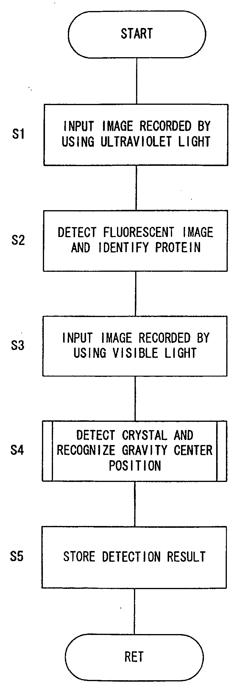
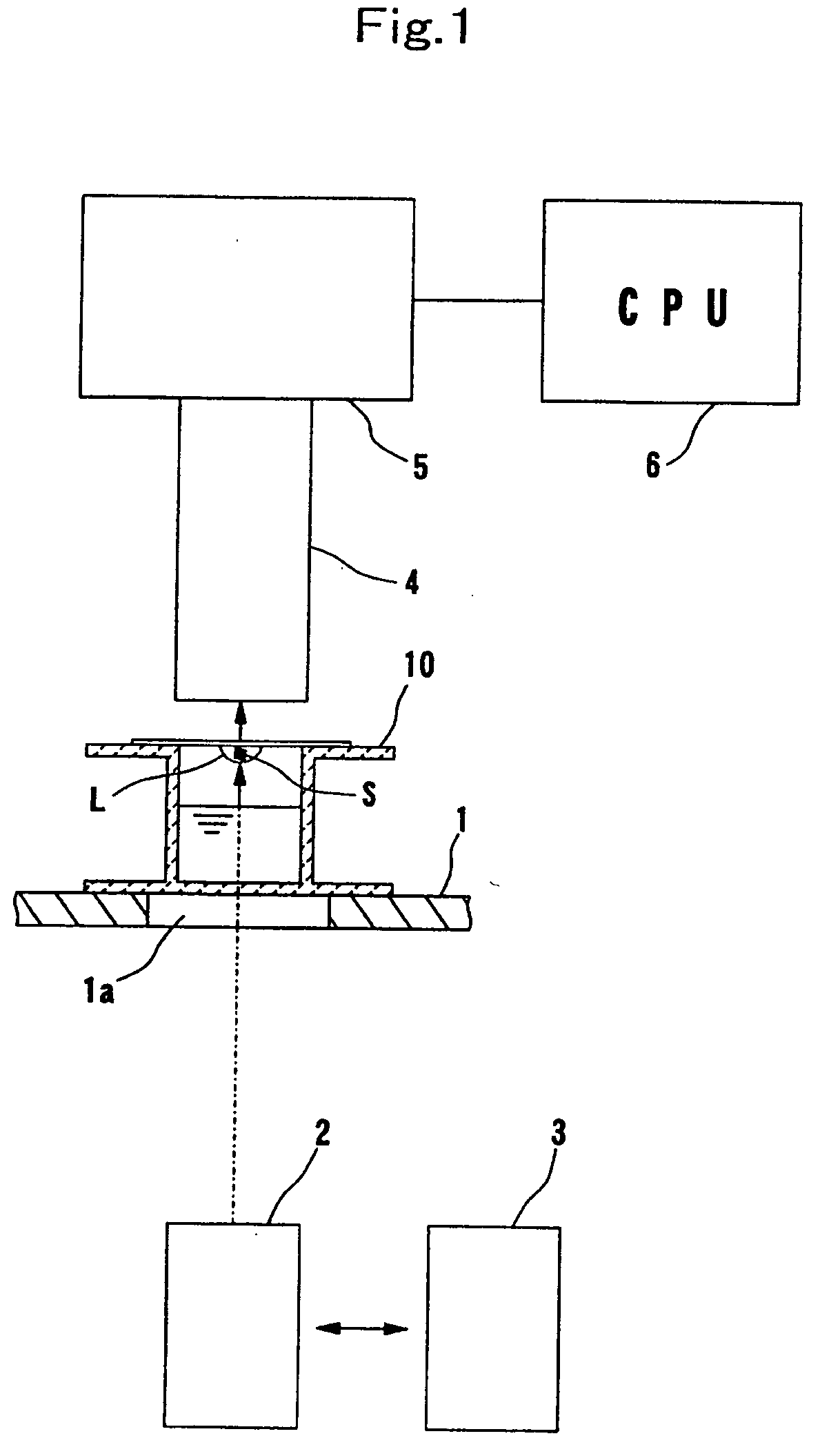
In a specific macromolecule crystal detecting method according to the present invention, ultraviolet light is irradiated to sample solution, and a fluorescent image emitted from a sample in the sample solution is detected to detect specific macromolecules in the sample solution. Furthermore, by detecting the outline of the sample from the visible light image of the sample contained in the sample solution, the crystal is discriminated from other materials on the basis of the outline. By integrating the detection results of the fluorescent image and the visible light image, the specific macromolecule crystal is detected from the sample solution.

Description

BACKGROUND OF THE INVENTION [0001] The present invention relates to a detection method of detecting a specific polymer crystal, namely a specific macromolecule crystal in sample solution. [0002] Worldwide attention has been paid to the structural analysis of protein crystals in connection with the development in the genome plane since a double helix structure of DNA was discovered. A method using NMR (Nuclear Magnetic Resonance apparatus) a method using an electron microscope, a method using the X-ray diffraction phenomenon, etc. have been developed for the structure analysis of protein crystals, and particularly the X-ray crystal structure analysis using the X-ray diffraction phenomenon has been rapidly advanced in connection with the developments of a two-dimensional X-ray detector such as an imaging plate or the like, analyzing software for two-dimensional data, etc. [0003] In the protein crystal structure analysis using the X-ray diffraction phenomenon, it has been hitherto gene...

Claims


Application Information

Patent Timeline
Patent Type & Authority Applications(United States)
IPC IPC(8): G06K9/00G01N23/20G01N21/64
CPCG01N21/6452G01N21/6486G01N21/6458
Inventor YAMANO, AKIHITOSATO, TAKAHISAYOSHIDA, HIROKIYOSHIMURA, MOTOHIDEHAMADA, KENSAKU
Owner RIGAKU CORP
Learn More