Eureka AIR delivers breakthrough ideas for toughest innovation challenges, trusted by R&D personnel around the world.

Aerobic and anaerobic waste management systems and methods for landfills

a waste management system and anaerobic technology, applied in the field of aerobic and, can solve the problems of reducing the total land area required to host increasing the difficulty of allowing new landfills and landfill expansions, and increasing the cost of constructing new or expanded landfills, so as to prevent leakage and seep into the surrounding environment, minimize liquid infiltration, and maximize the effect of disposal capacity

Active Publication Date: 2006-10-05
CASELLA WASTE SYSTEMS
View PDF11 Cites 24 Cited by
  • Summary
  • Abstract
  • Description
  • Claims
  • Application Information

AI Technical Summary

Benefits of technology

[0006] It is widely accepted that introduction of liquids (e.g., leachate, gas condensate, non-hazardous liquid wastes, storm water, surface water, groundwater) into a landfill accelerates the degradation of the organic fraction of solid waste compared to the dry tomb method. Faster anaerobic degradation of the organic waste results in an increase in landfill gas production and a subsequent rapid settlement of the waste. Rapid settlement of the waste results in increased effective waste density and recaptured landfill air space. With the proper management of liquids in the landfill, it is estimated that the amount of air space in a landfill that may be recaptured is in the range of about 15% to about 30%. The ability to reuse the air space gained from waste settlement may also reduce the total land area required to host new or expanded landfills. The resulting increase in the amount of waste that can be disposed of also results in an increase of the amount of gas as well as gas production that can be economically recovered for beneficial uses and control of emissions.

Problems solved by technology

As waste generation continues to grow faster than population, and permitting new landfills and landfill expansions is becoming increasingly more difficult and more expensive, leaders in municipal solid waste services must respond to the challenges of maximizing disposal capacity.
The ability to reuse the air space gained from waste settlement may also reduce the total land area required to host new or expanded landfills.

Method used


Image

  • Aerobic and anaerobic waste management systems and methods for landfills
  • Aerobic and anaerobic waste management systems and methods for landfills
  • Aerobic and anaerobic waste management systems and methods for landfills

Examples


Embodiment Construction

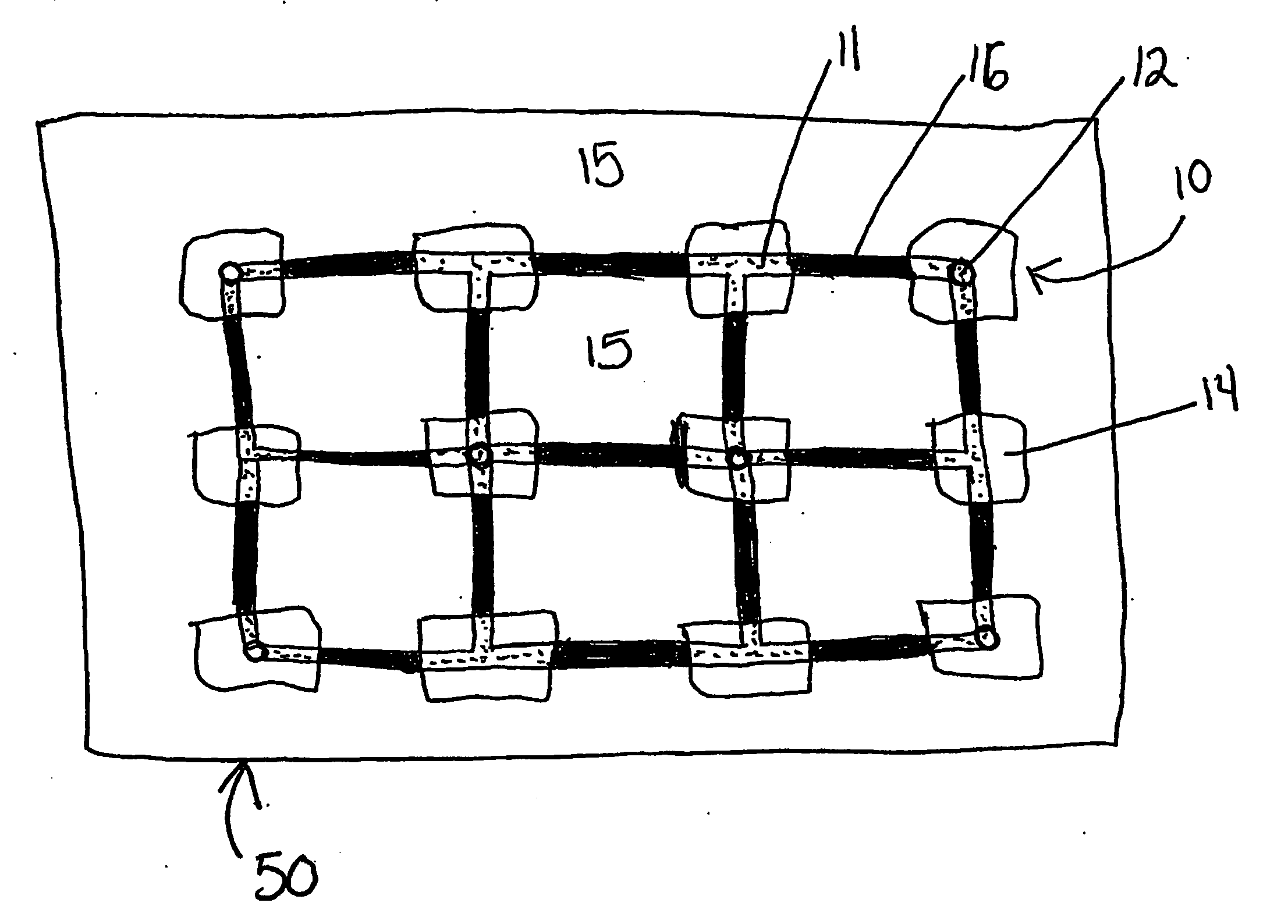
[0024] The invention provides systems and methods for creating, managing and staging aerobic and / or anaerobic landfills. The invention provides methods for collecting liquids from and recirculating liquids into landfills and methods for collecting gases from and introducing gases into landfills.

[0025] Liquids may be applied to landfills on a continuous or an intermittent basis in order to maintain the landfill moisture content in a range from about 20 wt % to about 65 wt %; or from about 35 wt % to about 55 wt %. In arid regions, moisture can typically only be increased from about 10 wt % to about 20 wt % because the starting waste moisture content is very low. The moisture content of the waste can lie outside this range depending upon the moisture holding capacity of the waste and the purpose for adding liquid to the landfill. In one embodiment, liquids are added to the landfill in an amount of about 10,000 to about 20,000 gallons / day for each 1,000 tons / day of waste brought into ...


PUM


Abstract

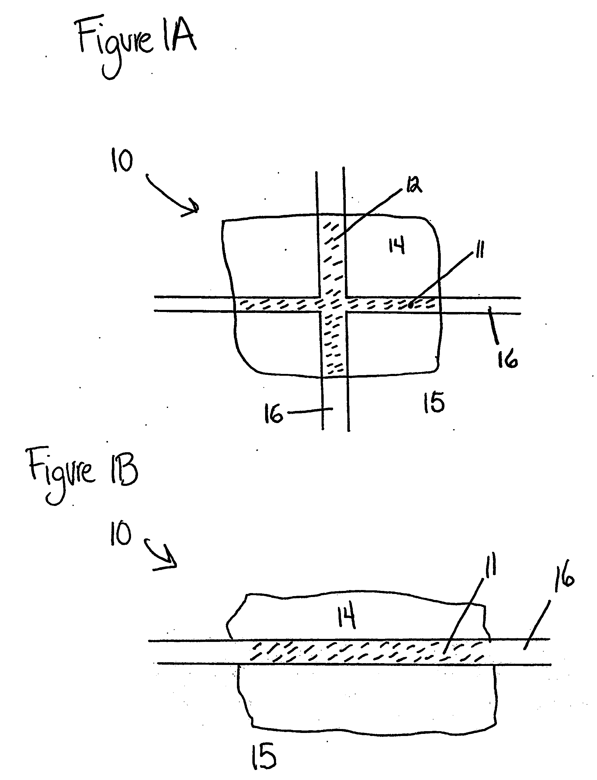
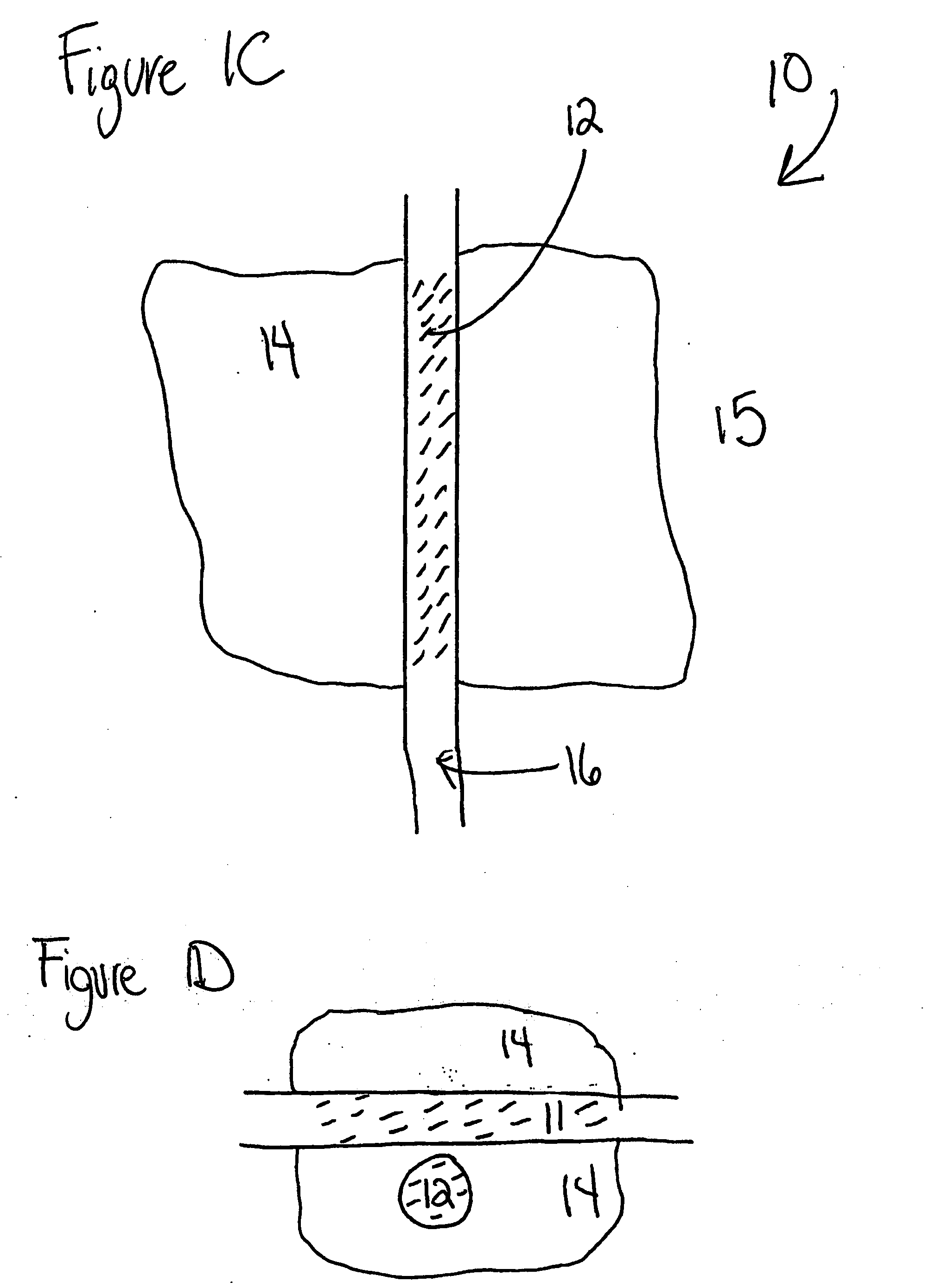
The invention provides systems and methods for creating, managing and staging aerobic and / or anaerobic landfills. The invention provides systems and methods for collecting liquids from and recirculating liquids into landfills and systems and methods for collecting gases from and introducing gases into landfills. The invention also provides a novel conduit for conveying liquids and gases which comprises a first pipe coaxially disposed within a second pipe.

Description

FIELD OF THE INVENTION [0001] The invention provides systems and methods for creating, managing and staging aerobic and / or anaerobic landfills. The invention provides systems and methods for collecting liquids from and recirculating liquids into landfills and systems and methods for collecting gases from and introducing gases into landfills. The systems and methods of the invention can be retrofit into existing landfills or they can be used in new landfill construction. BACKGROUND OF THE INVENTION [0002] The recovery of landfill gases including light hydrocarbons such as methane has become commonplace and is regulated under New Source Pollution Standards (NSPS). It used to be common to bum gasses vented from landfills. It is, however, becoming more common to use landfill gases to generate heat and / or electricity. Prior methods have resulted in increased costs and risks associated with managing gases and liquids in landfills. [0003] Landfill leachate, the aqueous solution that accumu...

Claims


Application Information

Patent Timeline
Patent Type & Authority Applications(United States)
IPC IPC(8): B09B1/00B65F5/00
CPCB09B1/006B09B1/00
Inventor SCHWALBE, JOHN
Owner CASELLA WASTE SYSTEMS
Why Eureka
Eureka Blog
Learn More