Turbine blade cooling system having multiple serpentine trailing edge cooling channels

a cooling system and turbine blade technology, applied in the field of turbine blades, can solve the problems of reducing the useful life affecting the cooling efficiency so as to reduce the amount of cooling fluid flow, increase the efficiency of the cooling system of the turbine blade, and reduce the effect of heat reduction

Inactive Publication Date: 2006-10-05
SIEMENS ENERGY INC
View PDF22 Cites 33 Cited by
  • Summary
  • Abstract
  • Description
  • Claims
  • Application Information

AI Technical Summary

Benefits of technology

[0005] This invention relates to a turbine blade cooling system formed from at least one cooling fluid cavity extending into an elongated blade and two or more serpentine trailing edge cooling channels in parallel with each other in the trailing edge of the turbine blade and in communication with

Problems solved by technology

In addition, turbine blades often contain cooling systems for prolonging the life of the blades and reducing the likelihood of failure as a result of excessive temperatures.
However, centrifugal forces and air flow at boundary layers often prevent some areas of the turbine blade from being adequately cooled, which results in the formation of localized hot spots.
Localiz

Method used


Image

  • Turbine blade cooling system having multiple serpentine trailing edge cooling channels
  • Turbine blade cooling system having multiple serpentine trailing edge cooling channels
  • Turbine blade cooling system having multiple serpentine trailing edge cooling channels

Examples


Embodiment Construction

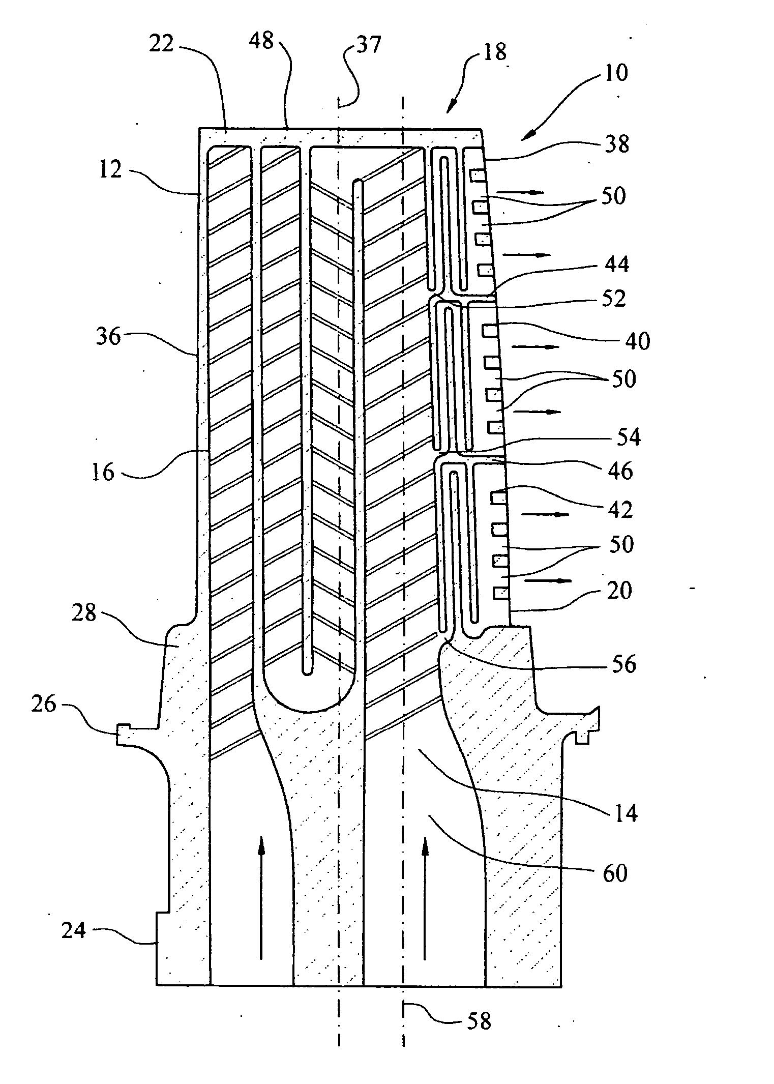
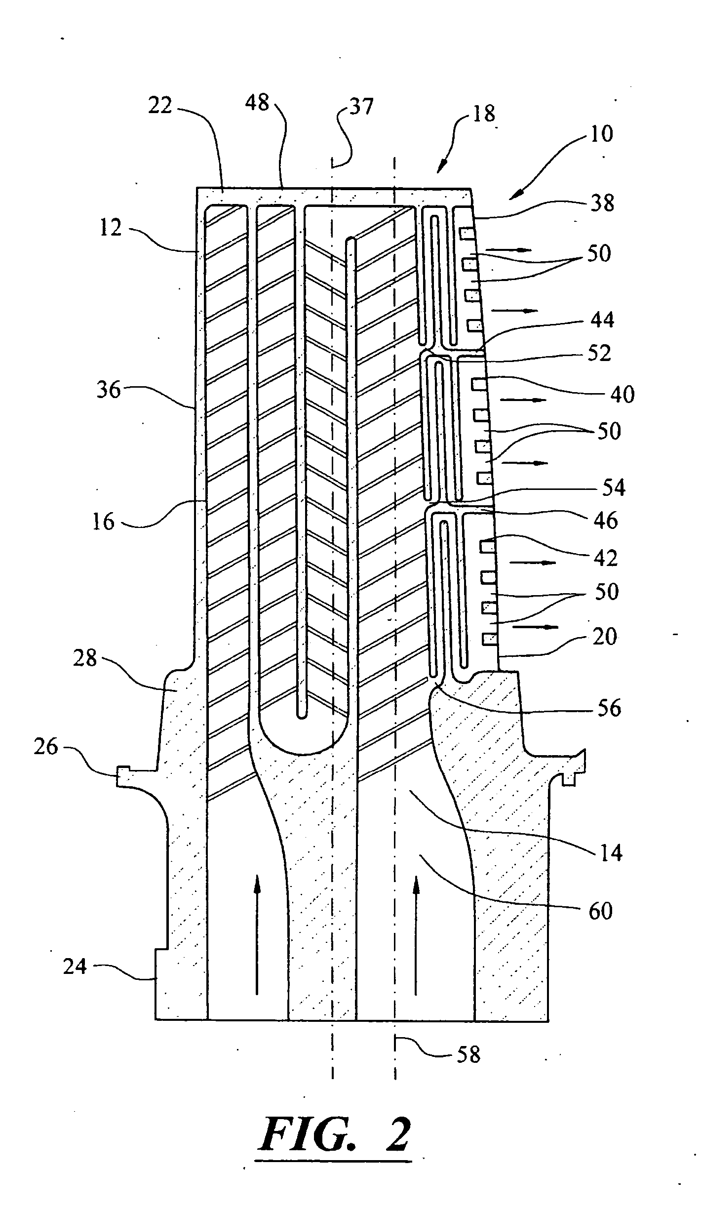
[0020] As shown in FIGS. 1-5, this invention is directed to a turbine blade cooling system 10 for turbine blades 12 used in turbine engines. In particular, the turbine blade cooling system 10 is directed to a cooling system 10 located in a cavity 14, as shown in FIGS. 2 and 3, positioned between two or more walls 28 forming a housing 16 of the turbine blade 12. The cooling system 10 may include two or more serpentine trailing edge cooling channels 18 positioned in parallel with each other in the cooling system, as shown in FIGS. 2-5, and in close proximity to a trailing edge 20 of the blade 12 for increasing the heat removal from the blade 12 and reducing the required cooling fluid flow to achieve adequate cooling, thereby increasing the effectiveness of the cooling system 10.

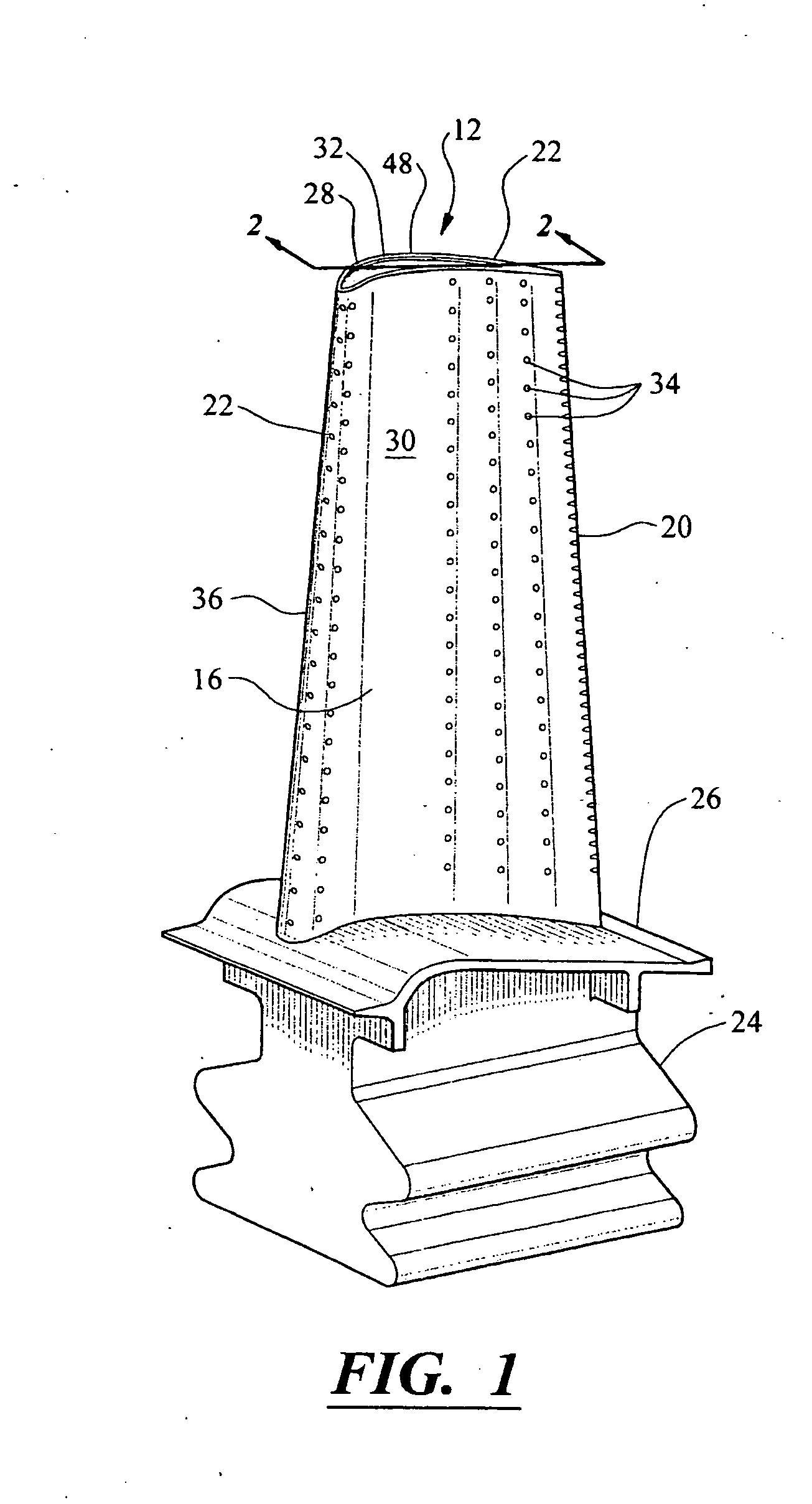
[0021] As shown in FIG. 1, the turbine blade 12 may be formed from a generally elongated blade 22 coupled to a root 24 at a platform 26. Blade 22 may have an outer wall 28 adapted for use, for example, in a fi...


PUM


Abstract

A cooling system for a turbine blade of a turbine engine having multiple serpentine trailing edge cooling channels in parallel. The serpentine cooling channels are positioned proximate to a trailing edge of the turbine blade and facilitate increased heat removal with less cooling fluid flow, thereby resulting in increased cooling system efficiency.

Description

FIELD OF THE INVENTION [0001] This invention is directed generally to turbine blades, and more particularly to cooling systems in hollow turbine blades. BACKGROUND [0002] Typically, gas turbine engines include a compressor for compressing air, a combustor for mixing the compressed air with fuel and igniting the mixture, and a turbine blade assembly for producing power. Combustors often operate at high temperatures that may exceed 2,500 degrees Fahrenheit. Typical turbine combustor configurations expose turbine blade assemblies to these high temperatures. As a result, turbine blades must be made of materials capable of withstanding such high temperatures. In addition, turbine blades often contain cooling systems for prolonging the life of the blades and reducing the likelihood of failure as a result of excessive temperatures. [0003] Typically, turbine blades are formed from a root portion at one end and an elongated portion forming a blade that extends outwardly from a platform coupl...

Claims


Application Information

Patent Timeline
IPC IPC(8): F01D5/18
CPCF01D5/187F01D5/20F05D2240/122F05D2260/2214F05D2250/185F05D2260/22141F05D2240/304F05D2260/204
Inventor LIANG, GEORGE
Owner SIEMENS ENERGY INC
Why Eureka
Try Eureka