Method for evaluating orientation state of oriented layer, method for manufacturing liquid crystal panel, and method for inspecting liquid crystal panel

a technology of oriented layer and orientation state, which is applied in the direction of thin material processing, instruments, chemistry apparatus and processes, etc., can solve the problems of limiting the thickness of samples, difficult to determine the orientation state of oriented layer in detail, and low sensitivity of this method, so as to facilitate the determination

Inactive Publication Date: 2006-10-05
SEIKO EPSON CORP
View PDF3 Cites 4 Cited by
  • Summary
  • Abstract
  • Description
  • Claims
  • Application Information

AI Technical Summary

Benefits of technology

[0018] This facilitates making a determination as to whether the cause of the fa

Problems solved by technology

However, the above-described technique using infrared spectroscopic ellipsometry suffers from a shortcoming in that measurements are dependent on the thickness of a sample and a requirement for the thicknesses

Method used


Image

  • Method for evaluating orientation state of oriented layer, method for manufacturing liquid crystal panel, and method for inspecting liquid crystal panel
  • Method for evaluating orientation state of oriented layer, method for manufacturing liquid crystal panel, and method for inspecting liquid crystal panel
  • Method for evaluating orientation state of oriented layer, method for manufacturing liquid crystal panel, and method for inspecting liquid crystal panel

Examples


experiment examples

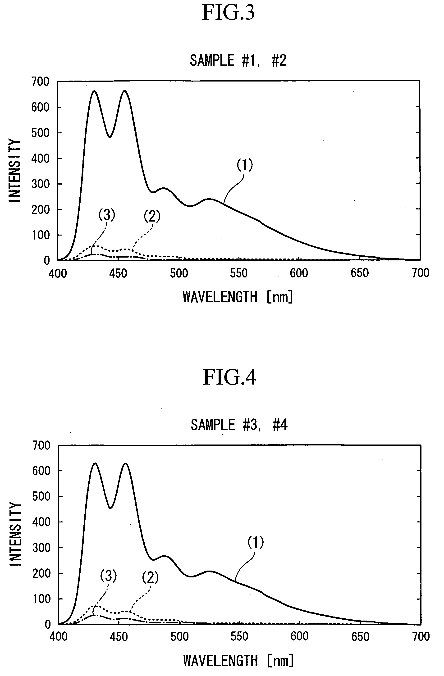
[0054] The correlation between the degrees of orientation (orientation state) of oriented layers and the orientation parameters f20, obtained from light emitting polymer films described above was confirmed through experiments.

[0055] Eight samples were prepared by forming a film of ITO on a glass substrate and forming a polyimide film (oriented layer) thereon. Next, these samples were subjected to a rubbing treatment under four different conditions (rubbing intensity conditions) described below. It should be noted that two samples were rubbing treated under each condition.

[0056] Samples #1 and #2 Rubbing intensity: “Strongest”

[0057] (Number of rotations of roll: 500 rpm and rubbing table shift speed: 20 (mm / sec))

[0058] Samples #3 and #4 Rubbing intensity: “Medium”

[0059] (Number of rotations of roll: 300 rpm and rubbing table shift speed: 120 (mm / sec))

[0060] Samples #5 and #6 Rubbing intensity: “Weak”

[0061] (Number of rotations of roll: 200 rpm and rubbing table shift speed: 200 (...


PUM

PropertyMeasurementUnit
Fluorescenceaaaaaaaaaa

Abstract

A method for evaluating an orientation state of an oriented layer, comprising: applying, on the oriented layer, a solution of a light emitting polymer containing a fluorescent material that is capable of being oriented according to an orientation state of an underlying layer; performing a heat treatment on the applied solution of the light emitting polymer to form a light emitting polymer film; obtaining a polarized fluorescence spectrum of the light emitting polymer film; determining an orientation parameter using an orientation function equation based on the polarized fluorescence spectrum; and evaluating the orientation state of the oriented layer using the orientation parameter.

Description

CROSS-REFERENCE TO RELATED APPLICATION [0001] Priority is claimed on Japanese Patent Application No. 2005-093625, filed Mar. 29, 2005, and Japanese Patent Application No. 2005-343339, filed Nov. 29, 2005, the contents of which are incorporated herein by reference. BACKGROUND [0002] 1. Technical Field [0003] As a method for evaluating the orientation state of a thin film of molecules exhibiting an anisotropic molecular orientation, such as an oriented layer using in a liquid crystal apparatus which are imparted with an initial orientation of liquid crystal molecules, infrared spectrophotometry that employs linearly polarized infrared light has been widely used (see Arafune et. al, Appl. Phys. Lett., 71, 2755, p. 1997, for example). This technique measures the difference in a relative angle between the polarization direction of the intensity of infrared light that is transmitted through a sample (oriented layer) formed on a substrate and the sample direction with respect to the relati...

Claims


Application Information

Patent Timeline
IPC IPC(8): C09K19/52C09K19/38
CPCG02F1/1309Y10T428/10Y10T428/1023G02F1/1337C09K2323/00C09K2323/027
Inventor TAKEI, ETSUKOHIRAIWA, TAKASHI
Owner SEIKO EPSON CORP
Why Eureka
Try Eureka